Site Links
Howdy, Stranger!
It looks like you're new here. If you want to get involved, click one of these buttons!
Quick Links
Categories
In this Discussion
Who's Online (0)
MAC Crossover Review Thread

Although there are build threads that ask questions about the crossover when the time comes, I see a lot of threads started to ask a simple xo question. These threads usually end up with about 5 posts and then die, to be repeated again and again by different posters. I thought it might be useful to have a running thread for simple/quick xo review questions.


Comments
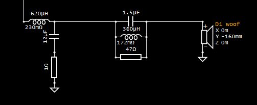
I am attempting an LR8 crossover for a 2-way. (InDIYana 2023 tweeter Yoga). The curves look okay to me. But I have seen some comments about the magnitudes of certain components that may create issues. I don't know what the issue was, but I assume some combination of low valued and really high-valued inductors and capacitors that don't react well to each other. (??)
Do you see any issues with the xo below?
[Edit: These are actual in-box measurements of the drivers at 1m put into VituixCAD. I show down to 25db because this is a metal dome midwoofer and I wanted to make sure the breakup is 50db down.]
I'd start by looking at the impedance/phase plot. In general you don't want a low impedance at the same time the phase approaches the 45 degree range. Rod Elliot has a good article about it at https://sound-au.com/patd.htm. Here's a chart from Rod's article that shows at 45 degrees phase the amp has to double it's output. If that occurs when the impedance is low the overall current load on the amp is multiplied.
First step to designing a successful crossover is to gather accurate data. VituixCAD provides invaluable detail of power & DI and polar maps so you don't have to make assumptions, generalizations, or guesswork for what the outcome of a crossover might be, at least as far as amplitude response goes. HD would be the other consideration. Given just a single on-axis response, without additional information of phase, power & DI, filter transfer function, etc. There's not much to say about this crossover other than high order filters are often not needed, metal cone breakup is best addressed with a notch over a high order filter, and 50dB down is a bit extreme, 40dB would be 1% of pass-band, 50dB 0.3%.
This is a good topology for a woofer filter.
It's not clear from the information provided if a timing reference is used, or single channel USB mic. For the best chance of success, I recommend following the measurement guide(s) for VituixCAD and gathering the full spatial data. For evaluation of the crossover, provide the full 6-pack of information.
This is just my my first simulation after taking measurements. I typically start with a flat on-axis response with each driver close to target curves. I check phase and impedance and then save as Variant #8 as a starting point that I can go back to if needed. THEN I start tweaking and looking at the power, DI, polar maps, etc.
I probably shouldn't have even posted the on-axis response. I also have an LR4 version and will look at the topology that you posted. I have an okay idea what the LR4 topology should look like, but trying to hit the LR8 target I really had no idea if those big 47uf and 33uf caps in the woofer circuit for example were normal or not, of if I was way off base with some of these component values.
Yes, I have 0 to 180 degree measurements at 10 degree increments, using your old EMM-6 with OM1 calibration file") and a Steinberg Mkii preamp.
and a Steinberg Mkii preamp.
Comparing my 8th order Zonker xover, I'd say you are probably right on target with 47 & 33uF caps in the woofer branch. My Zonker's use 47 & 30uF in the same spots. My inductors, however, are much larger (3.5 & 3mH), as I am crossing at 910Hz (tweeter yoga to the max!)")
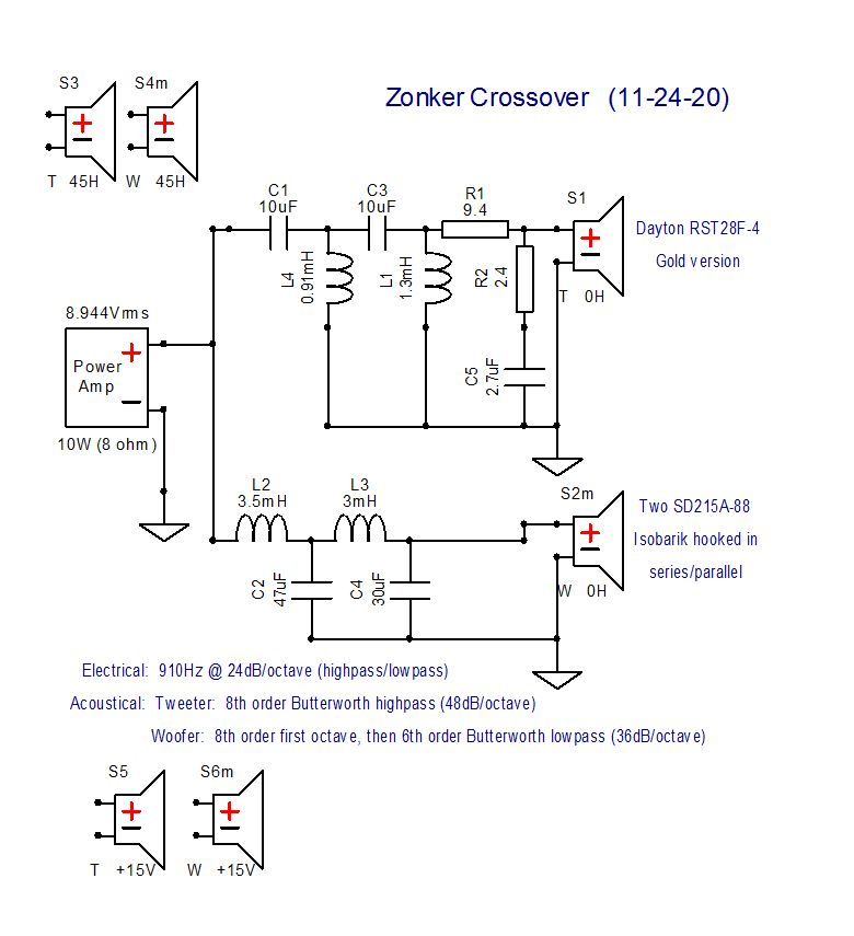
EDIT: I should mention, I built the zonkers before I had completed my two channel measurement system, so who knows what my power response or In-room response curves look like. Could be a real mess.
Great, sorry I forgot who that went to.
Once you've got the full 360 degrees of information loaded into VituixCAD, I usually set a crossover topology that I think will work, and manually adjust part values to get a crossover in the ball park. Then move on to the optimizer for fast-track fine tuning, with the following settings:
Optimize by listening window and in-room response, at 50/50 weight
set listening window target slope at -0.15dB/oct from 100Hz to 10kHz
set in-room response target slope at about -0.8 to -1dB, depending on the speaker, basically draw a trend line from ~300Hz to 10kHz, and use ~300Hz - 10kHz as the optimizer frequency range.
minimum impedance 3 ohms, E24 snap to stick with part values you can buy.
Based on parts on hand I may lock part values in and re-optimize to target only specific components, and adjust crossover topology and redo above process for several comparative options, save each as a crossover variant for quick and easy comparison. For system optimization, often does not work well for inclusion of notch filters, so that may require some manual adjustment or avoid including those parts for optimization. Optimizer works best if part values are in the ball park to begin with, and frequency range for optimization is limited to the area you want to target the most.
You may also try optimizing by listening preference rating as well, which includes a lot more options for defining the target response, however I find it usually doesn't change the response much from the above target for listening window and in-room response.
I find it difficult to glance at a x-o and interpret it when different units are used.
That said I don't see anything wrong with the the x-o shown. I would optimize it differently with notches to get to eighth order but that's me. I've also gotten away from small shaping inductors on the tweeter. I think it kills the off axis response.
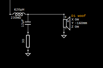
I look at the impedance when using large caps on the woofer and play with the the inductor and cap to get the impedance where I want it. A small resistor with the cap can also change the slope and damp any bump at the knee.
The resistor on the woofer cap will not change the inherent slope. It will change the contour or knee shape, but not the inherent slope.
InDIYana Event Website
Small value will not affect slope greatly, larger value definitely will.
I would be a little concerned that the 1+ dB deficit in SPL below 500Hz will make the system sound thin/bright. If anything I would shoot for 1dB elevated response below about 300Hz. More inductor, more inductor!
They are still all inherently 12dB slopes.
InDIYana Event Website
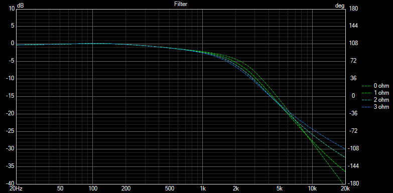
Measured from 3500Hz - 7kHz
0 ohm 11.8dB
1 ohm 10.7dB
2 ohm 9.2dB
3 ohm 8.1dB,
With 0 ohm, slope beyond the knee remains fairly constant at all frequencies. Adding the resistor puts a curve in the slope by reducing the effectiveness of the capacitor. The larger the resistor value, the closer the response approaches that of a single order filter.
I understand what you are saying. Let me tell you what my intention was and see if it makes sense (that is, makes logical sense, not that it will necessarily sound good).
I was attempting to only have 4.5 to 5 db baffle step compensation. The reasoning is that for the theme competition at InDIYana and often at Midwest Audio Fest, speakers without full BSC typically do well. This speaker will be entered in the 2023 theme competition and then the drivers removed and repurposed, so the goal isn't long-term great sound in my own listening room.
This speaker has a 9.5" wide baffle. Would the SPL curve above reflect a speaker with only 4.5 to 5 db BSC, or am I misinterpreting that?
That looks like about 4dB of BSC to me, on the assumption that your entire model is quasi-anechoic.
So wrt the small resistor affecting the slope of the woofer at the knee, the changes are minor but help to improve phase alignment, in some cases significantly. It's a tool which is why I suggested using it.
Weeell crap.
I wouldn't be too concerned, and it could be small-sample bias. I know several builds at InDIYana and MWAF (and I think pretty much all of Paul Kittinger's) didn't have full BSC and last year's InDIYana winner (who finished his xo a few minutes before the competition) purposely didn't have full BSC. On the other hand, 90% of the winners over the last 10 years could have full BSC and I wouldn't know.
I have heard that many builders do not use full BSC. These systems will sound find in a modestly sized room due to room gain starting to kick in below 200Hz, which is not captured using quasi-anechoic measurements. YMMV
Yes, and it works quite well for such a task.
InDIYana Event Website
The reason they (speakers with less than full BSC) do well at events held in large rooms is kind of obvious. It is the equivalent of cranking brightness and color saturation up on televisions at Costco.
I thought you need full BSC (or more) for speakers in big room way out 10+ feet out from any walls. My speakers are typically 3-4 db of BSC or less if the woofer is lower, as I typically design and voice for nearer to the wall (18" or less) and they typically get shoved in one corner or the other. All my speakers (the very few I actually complete) end up in doing active duty so i prefer something that I actually use. Hence all the pushing shoving of the speakers closer to the walls in the DIY events in order to make the bass come up.
Wouldn't less BSC make the speakers seem anemic? I also prefer a gradual 2-3 db dip towards the high end starting around the 2-3khz - this may make the speakers seem less detailed, but is but to me is more pleasant to listen to.
Less BSC tips the balance up and they will appear more detailed, as JR said like turning up the brightness on a TV.
But what about the boom? Isn't More bass is more noticeable?
I always thought it was because they're being judged by a bunch of old guys with hearing loss
What does your hair loss have to do with this?
Mine are usually in the same boat, Ani. I tune for real world situations where speakers are usually very close to the walls/corners. This leaves them bass shy at events. I also prefer the BBC dip, which helps that issue a bit.
My Faux Pas build has pretty much no BSC. They begin to sound more balanced when nearly touching the wall in my small living room. Had my doubts they would sound good in the big room at inDIYana so I was planning to bring a different build instead. Though if folks really would want to hear them I guess my arm could be twisted. I've only got so much room in the vehicle though and towers with 12" woofers take up alot of it. If no chance for rain I suppose they could go in the truck bed.
The theme build I was designing for as much BSC I could get since it would be in a large room, likely feet from any wall. Was also shooting for a slight downward slope in response since that seems popular around here. For me, this is the first time really designing for other folks to hear, and in a much larger space than I have. So kindof a shot in the dark. Not that I expect to have any chance at actually "winning". Just want the first impression to not be of a total jackass. If I haven't done that already lol.
Perfect timing on the BSC and near-wall placement issues. I am trying to help someone out on diyaudio.com because they were about to use off-the-shelf crossovers
 whereas I had the drivers and measurement equipment. These are tiny 0.04 ft^3 speakers using the Fountek FE95 full range driver and Peerless DX20BF00-04 tweeter. He is going to use them on a mantle to the sides of his on-wall TV.
How would you design a crossover for such a case?
Below is my first stab, but not sure how to build in the necessary BSC for such a near-wall speaker. Also below is the VituixCAD diffraction that I was trying to use intuitively to guide by BSC.
Here's a quick test run on a small bookshelf. In my basement I have a ledge 8" deep , and the speaker is able to be placed flush to the ledge, so the front of the speaker is 8" from the back wall, but below the speaker the ledge is only about 1" back.
I compared this measurement to placing the speaker on the front edge of a table 2.5ft from the back wall. Measurements were unwindowed at 3ft distance, and smoothed 1/1 oct to show only the overall trend of the response graph.
I then completed magnitude division to show only the difference between these two measurements.
Take that information for what it is, just a quick and dirty comparison.
Another comparison, here's an inverted diffraction simulation compared against the above difference between on-wall vs far from wall placement.
If you consider 200-500Hz range as the "baffle step region", difference is about 2.5dB, so you could say that BSC for on-wall placement could be 3dB instead of 6dB, with some expected extra bass boom 50-100Hz.