Site Links
Howdy, Stranger!
It looks like you're new here. If you want to get involved, click one of these buttons!
Quick Links
Categories
In this Discussion
Who's Online (0)
Polk RTi100 cabinet reuse project
I acquired a pair of Polk RTi100 speakers which are built from 3/4" MDF and have a built in bandpass 6.5"sub with 35W amp. A quick measurement of the bandpass portion yields a rear chamber volume of .54 ft^3, a front chamber volume of .43 ft^3, and a 5.75" long x 3" diameter vent that comes out the bottom of the speaker. The upper front of the cabinet is ~ .2 ft^3 sealed for the midbass/tweeter. I also measured the woofer via DATS and plugged this into WinISD....
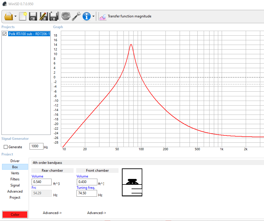
My plan is to build these into a 3 way speaker by removing the internal woofer and allow the ~ 1 ft^3 to be used by a front mounted driver. The mid and tweeter will use the same sealed chamber and I'll CAD a new mini baffle for the drivers. To utilize the stock grilles, a woofer that is 7" in frame diameter is a big as I can go. I have some RS180-4 that should work well. Here is where I have reached a crossroads, where to place the RS180 on the baffle? I wouldn't need to modify the grilles if I place the woofer up high, but they will interfere with the lower board of the sealed mid chamber. The scotch tape depicts its location. I can place the RS180 lower so it doesn't impact the upper sealed chamber, but I would have to modify the plastic grille for a RS180 cutout. It appears the cloth fastened to it using heat/melted, so it may not go back on easily.
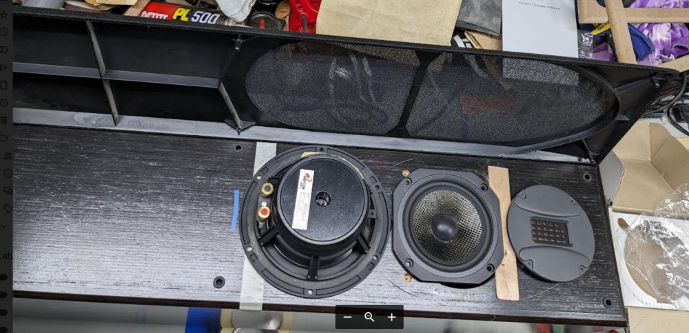
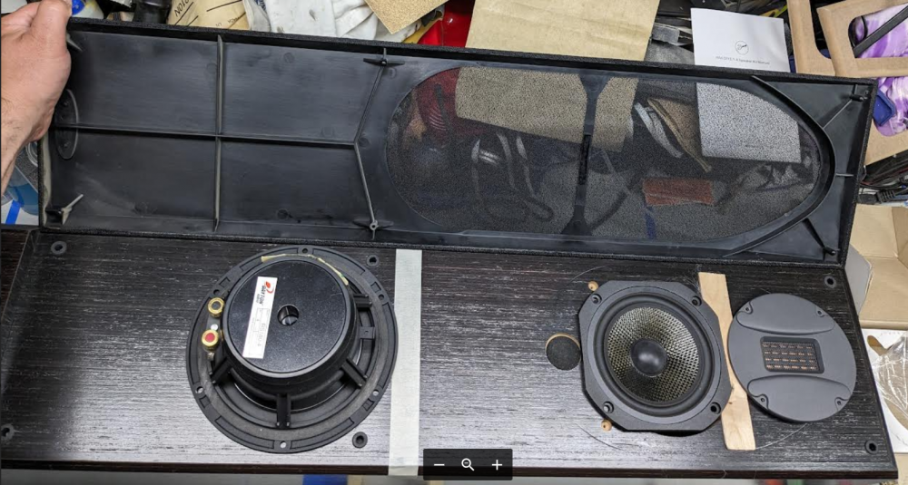
Suggestions?
Thanks!
Comments
I'd put the woofer down low and make a new grill.
Is that an Audax I spy?
+1 on woofer down low close to the floor. Roy Allison published some papers on this sort of configuration for 3-way loudspeakers in the 1970s IIRC. The woofer at the floor benefits from a decent amount of floor gain (e.g. almost 6dB), and this is useful up to about 300Hz, where he recommended to cross over to the midrange, which remains up high. The floor bounce of the midrange happens below 300Hz, and by crossing over at 300Hz or higher that is kept below the mid passband. It's a great way to solve the problem of the first null from the floor bounce that can make the midbass sound wrong. I even use this concept with dipole OB type loudspeakers.
Also, if you use a second order crossover between woofer and mid that will nicely fold into the baffle step compensation since the woofer will be +6dB ish WRT the mid and 300Hz is about typical for the midpoint of baffle step in many speakers of this design.
Yep, the Audax I bought from Charlie
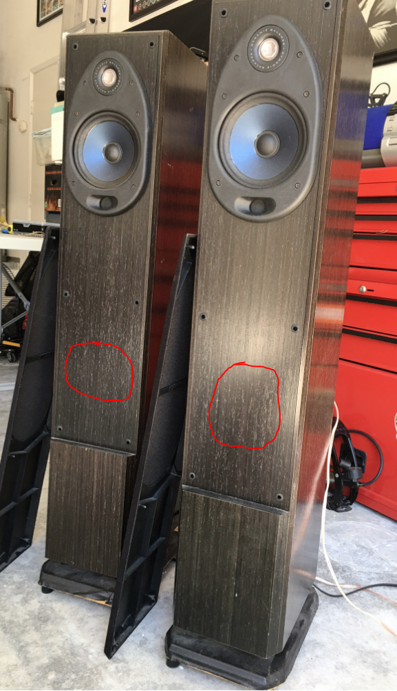
Thanks for your input. Here is a pic I pulled from the internet to see the full cabinet. I'll have to make sure I don't interfere with the port, but I could center it between the grill mounts.
Here is the new mini baffle I CADed up. Same width and overall height as the previous.
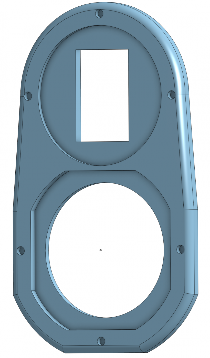
I like it!
Yup!
Making progress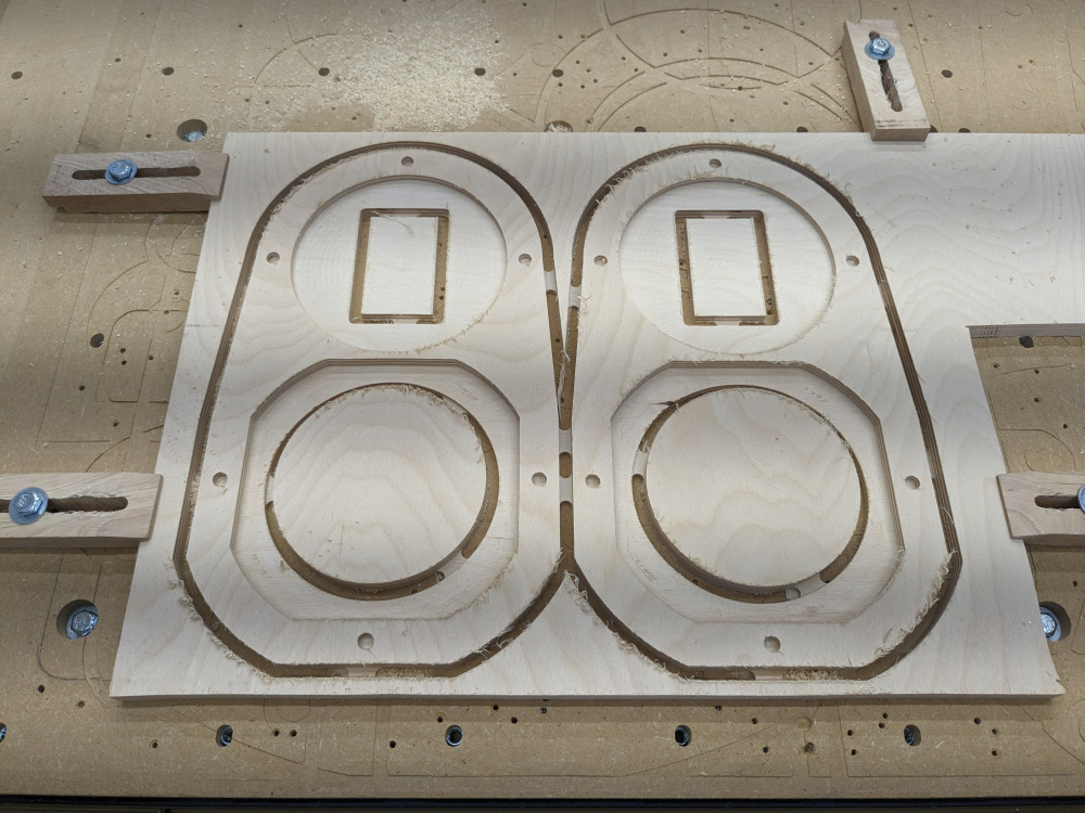
Routed the RS180 rebate, modified the cabinet for the new tweeter and mid rear ends, put a chamfer on the new M/T face plate as well as the rear plate that replaces the amp, removed the grille cloth and modified the plastic grill to accommodate the new drivers. Ordered new cloth and need to solder up the M/T crossover I'm using from Michael Chua. The woofer/mid crossover will be active via Camilladsp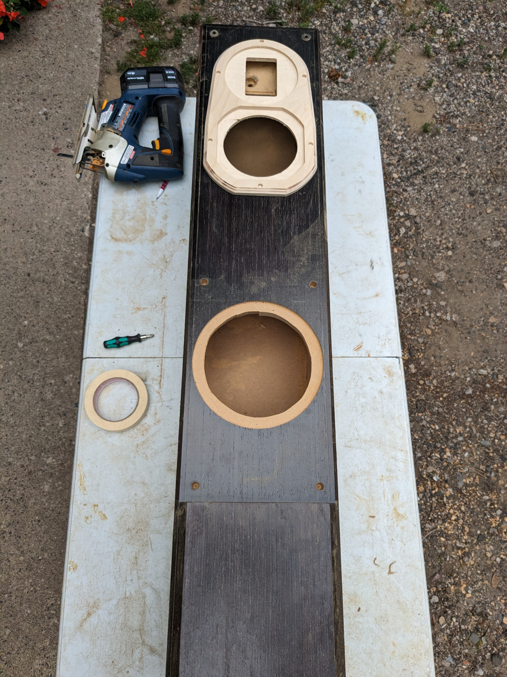
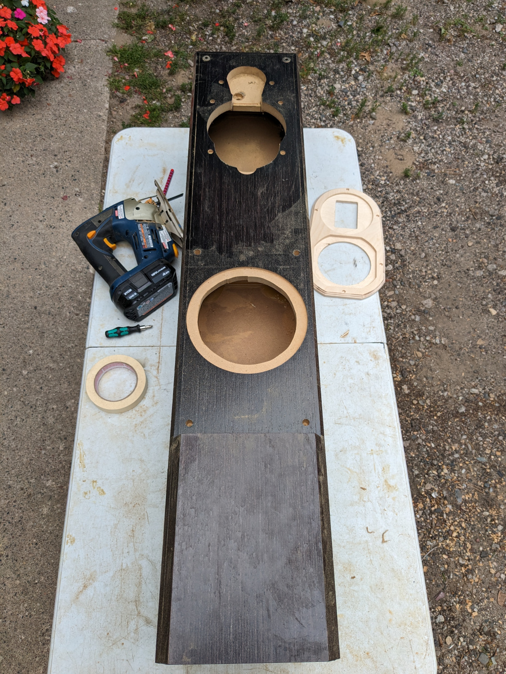
Will power these with my newly built 4 channel amp based on the the 50asx2 and 125asx2 modules and some VU meters.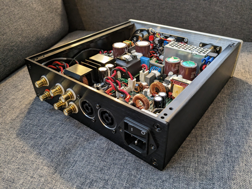
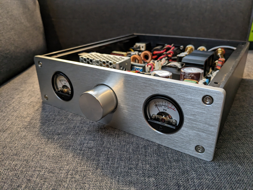
Wow! That amp looks nice - great work!!

Thanks Steve, but to be fair I bought the VU case then mounted and wired the modules and VU board and made the necessary rear plate modifications to support the needed connectors.
Here is the rear plate where the amp used to reside. I still need to finish securing the components to the board and solder.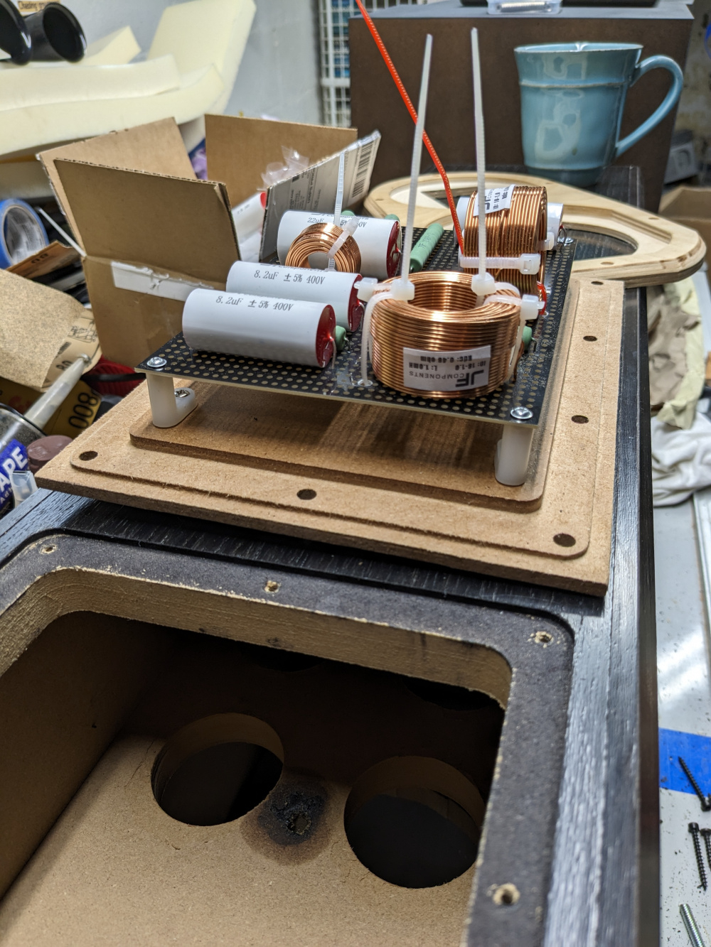
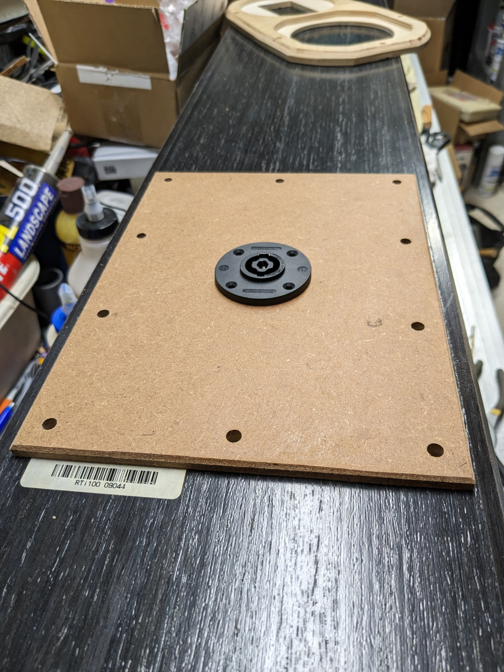
I updated the thread name now that the woofer placement was chosen.
Test fit drivers and grille, which still needs the woofer hole added.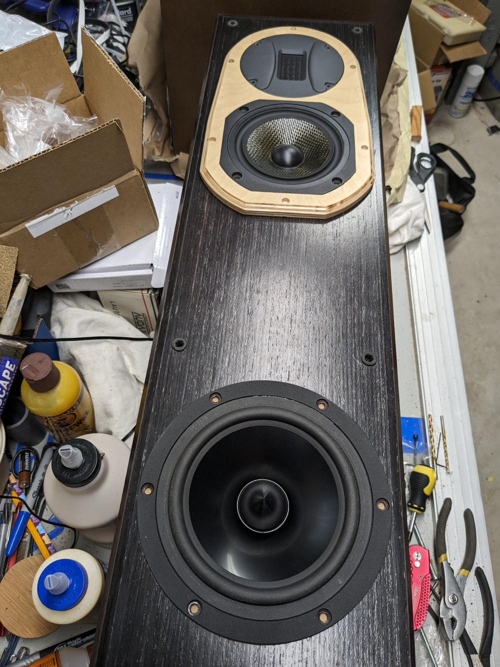
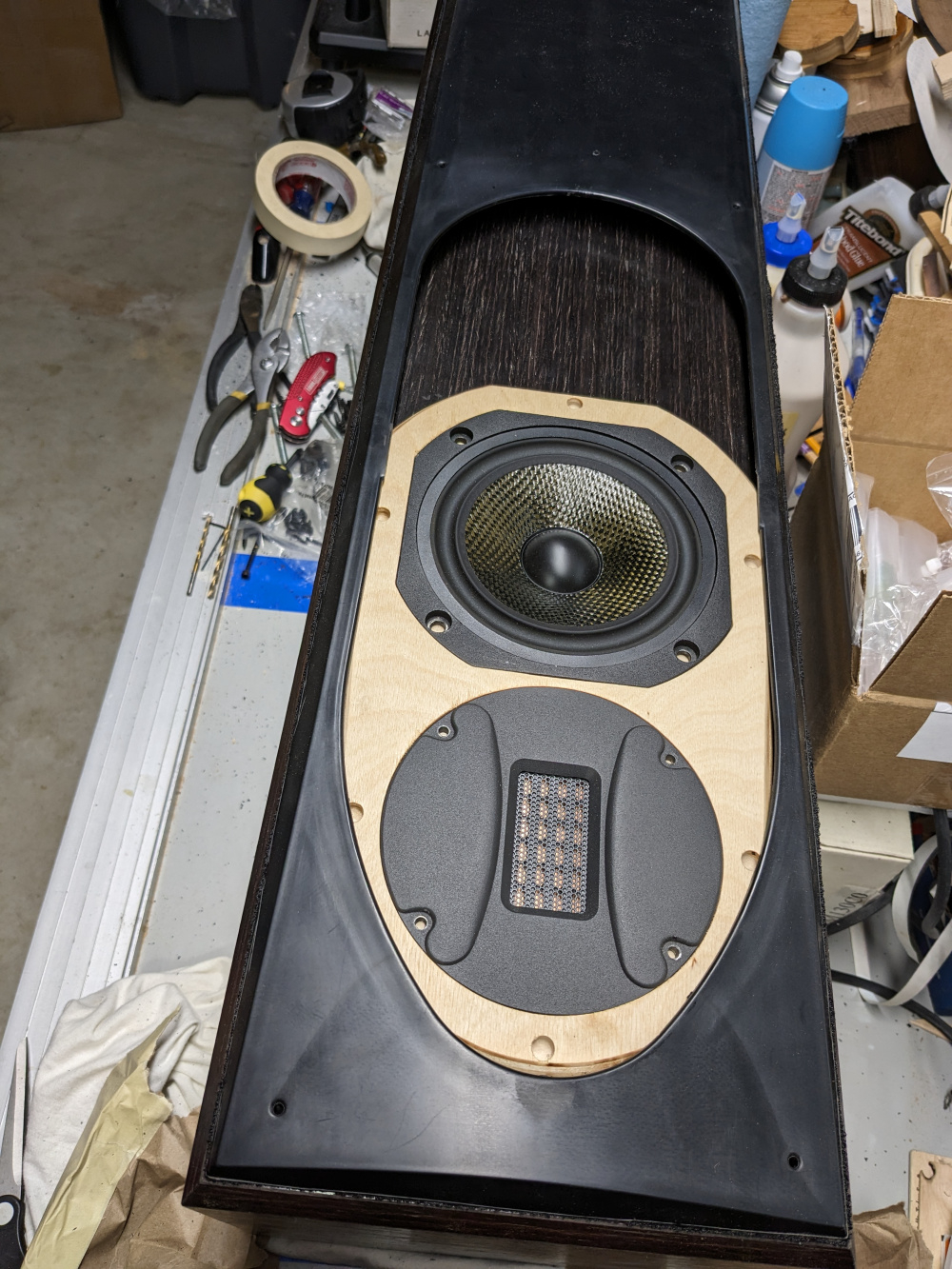
Would you mind sharing the cad file?
Not at all, what file type?
Here is the step, rename from .txt to .step
Can you do svg or dxf?
Sure can! Do you want the edge chamfer included?
No, that is not needed.
Here you go Rename to .dxf
Thanks!
Here are the impedance sweeps on the W and M/T. I didn't modify the port yet and modeled it at 35Hz, looks to be at 44Hz currently. Need to track down the resonance at 160Hz.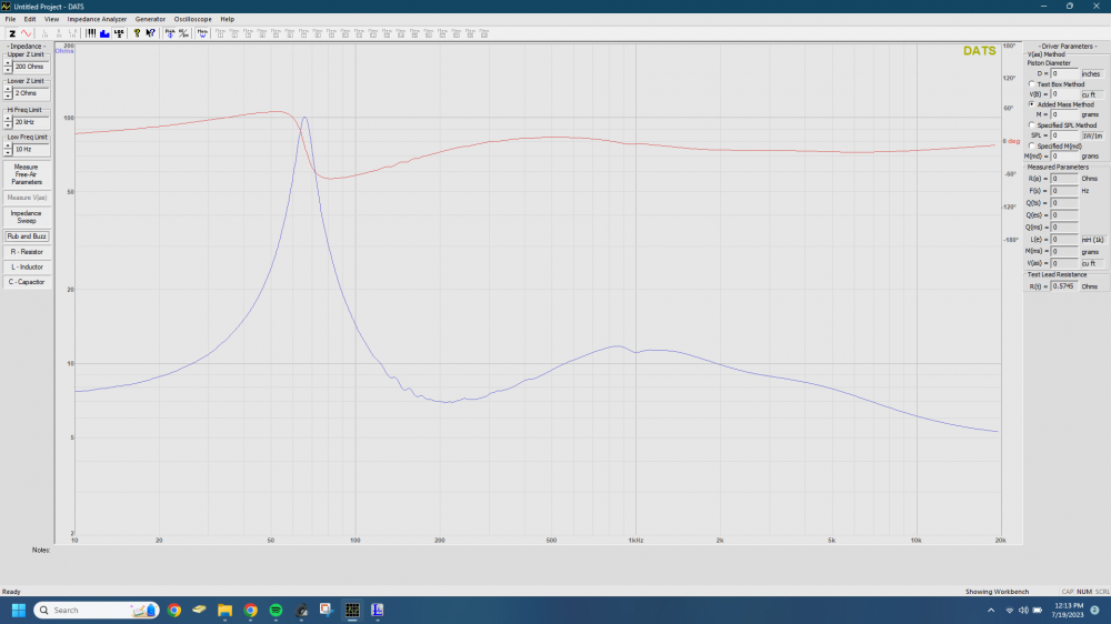
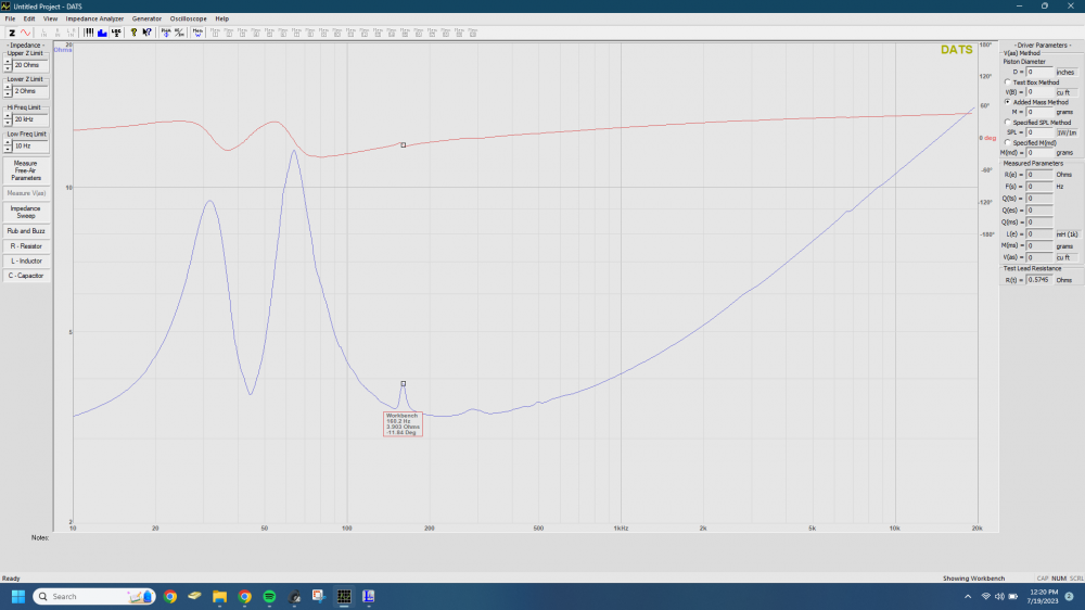
One up and running!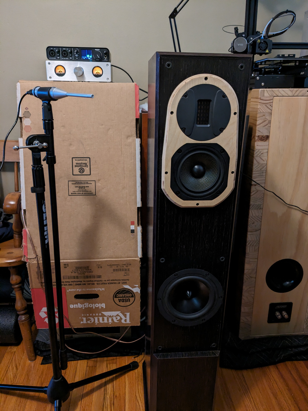
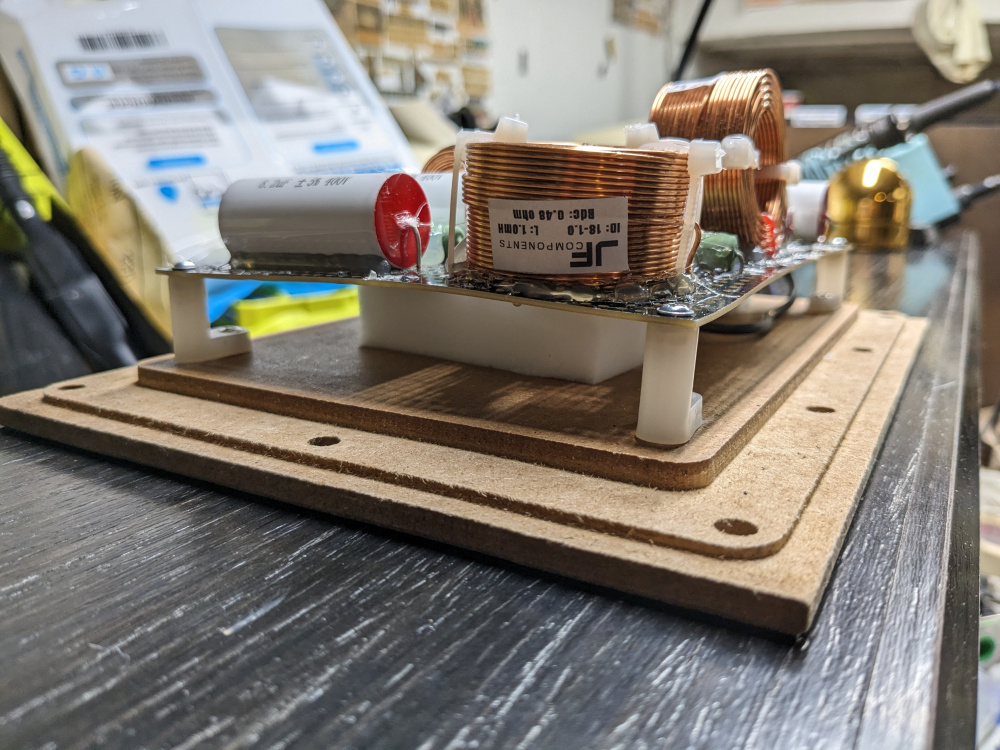
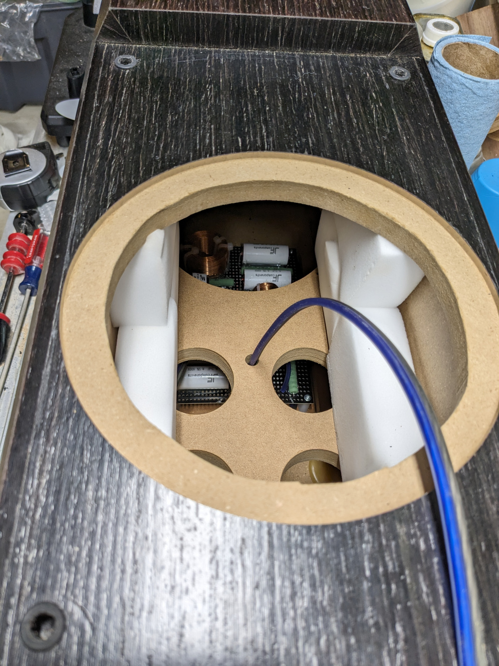
Looking good!
What CAM software are you using? Does it automatically make the tabs?
I'm not aware of any CAM that adds tabs but there are lots of CAD programs that do. Vetric has a very easy to use tab function.
This software looks like Fusion.
Great questions, I use my friend's Shapeoko 3XXL along with their Carbide Create and Motion software. I manually added the tabs before generating the gcode. I need to learn Fusion360 so I can cut the fillets and chamfers on the CNC vs manually.
Need any help with Fusion let me know. I'm o.k.
A question for the RT1.3WE users out there. I did a basic FR measurement and find there is a peak at 11.5kHz. Anyone else experience this and what kind of mitigation was used? I simply added a peaking biquad to knock it down, but maybe this is what people like about it? In the .frd I pulled down from PE, the peak is there, but seems higher than 11.5kHz.