Thanks, Bill! Problem fixed. Here is the output pegged on my interface and that gives me ~600mv with the output set at -12dB in the generator. Volume on the 6J1 is wide open giving me 1300mv into what amounts to about a 17k load impedance -
Fantastic! Good to see you got it running! 1.3Vrms at the output is a fairly high level, probably enough to drive many power amps to full output. I forgot to mention, before you click the red start button, you can also click on the small gear icon on the RTA screen and then switch from generating an RTA plot to generating a Spectrum plot instead. And then re-run the same test. This changes the slope of the noise floor and how the noise spikes average out over time.
I was curious as what square waves would look like going through my finished preamp, so I fed it some 0.700Vrms square waves at 20kHz, 1kHz, and 20Hz. The 20kHz and 1kHz square waves look perfect, but the 20Hz one has a slight upward slope. This is due to a slight rising frequency response below 40Hz, which is exactly what my measurements show on my REW FR plots. This does not, however, seem to be causing any type of audible problem. It just seems kind of interesting from a design and analysis standpoint. I wonder what could be causing this? I have also attached the sine wave output at 20Hz, which looks perfectly fine.
1kHz square wave, driving into a 18k ohm load. Preamp input: 0.700Vrms. Preamp output: 1.68Vrms:
20kHz square wave, driving into a 18k ohm load. Preamp input: 0.700Vrms. Preamp output: 1.67Vrms:
20Hz square wave, driving into a 18k ohm load. Preamp input: 0.700Vrms. Preamp output: 1.73Vrms:
20Hz sine wave, driving into a 18k ohm load. Preamp input: 0.700Vrms. Preamp output: 1.26Vrms:
@PWRRYD said:
What are the values of your C10 and C12? Are they still the stock 1 uF?
No, I boosted C10 and C12 to 3.3uF. I also boosted C9 and C11 from 1uF to 3.3uF. I think Tom also boosted his values of these coupling caps up to 3.3uF as well.
That looks really good, especially considering this is a bargain Chinese tube kit that many "experts" claim can't be any good since it's not running at an optimal B+ voltage. Interesting that you are seeing more rise at the low end than I am. I wonder if that's because we have slightly different parts in the feedback loop - or maybe it's just different tubes. I thought I had the same rise, but it turned out that I didn't have the cal file enabled in REW. I'll be working on my Arduino circuit today, so I'll have mine apart again. I'll try the 5654Ws and see if they measure the same as the 6J1s.
@Tom_S said:
Interesting that you are seeing more rise at the low end than I am. I wonder if that's because we have slightly different parts in the feedback loop - or maybe it's just different tubes. I thought I had the same rise, but it turned out that I didn't have the cal file enabled in REW. I'll be working on my Arduino circuit today, so I'll have mine apart again. I'll try the 5654Ws and see if they measure the same as the 6J1s.
Ya, I think you are on the right track. I'm using 100k in series with 0.22uF in my feedback loop. I only began getting the low frequency rise in my measurements AFTER I installed the feeback loop. It was flat to 30Hz and rolling off slightly by about -0.1dB at 20Hz before I installed the feedback loop. And, as Craig mentioned, this is certainly nothing to sweat about, as the circuit seems very stable (no ringing).
As an aside, I am trying to learn the circuit simulation program called LTspice. Setting up a model to simulate this simple 6J1 tube circuit seems like a perfect way to learn the program. So I downloaded LTspice version 17 and am running it through the gears on my laptop. I found a spice model for the 5654/6AK5/6J1 series of tubes in post #1079 of the DIYaudio thread entitled "Vacuum Tube Spice Models" (see link below). If I can get the program schematic set up and running properly with the 6J1 tube in place, then I should be able to tweak the feedback values to see what is causing the rise at low frequencies. The program allows you to feed in a square wave at 20Hz and then look at an oscilloscope output of the waveform. But, again, this would just be a simple project to learn the program, nothing else. Have you ever used this program?
Looks like you are geeking out tonight too! I'll have to look into LTspice. I had no idea it was from Analog Devices and it's free! I'm curious what you learn through modeling this tube.
I finally got my Arduino circuit working. This would have been child's play for any 1st year programmer, but it took me hours to figure out I needed to declare the pins sending the voltages to the motor driver as outputs.
I hadn't let the smoke out of anything in years, but I cooked the chip on the H-bridge when I dialed up the voltage to 12v. Whoops....actual smoke came out and burned a hole in the middle of the chip! Guess I should have looked at the spec sheet. I'll have to find a spot for another voltage regulator board, but I think that won't be a problem.
Happy New Year and try to stay safe! I always put on my safety glasses before I power up. Instead of smoke, sometimes you can get diodes acting like firecrackers.
Nice looking layout, Tom! You really have that small cabinet jam packed to the max! I was wondering what that aluminum angle bracket was going to be used for. I thought maybe that would be used to hold a hum shield to separate the two transformers from the audio PCB and cables. But now I see that you used it to mount three additional circuit boards on edge. Looks cool! So how does it sound?
I've only been able to listen to it for a few minutes, but it sounds fine. I can already say it's really nice to have the remote volume for when quiet songs pop up on my playlists. At some point, I'll have to add some other remote codes to the programming in case the old Sony remote I'm using dies.
I now have LTspice set up and working with the 6J1/5654 tube model. This allows me to tweak schematic values on the fly and run plots to show the effects on output impedance, frequency response, harmonic distortion, etc. The model seems to be giving me very accurate results so far. Here is a screen shot of my modified version of the preamp, showing the rising response below about 30Hz. This is a very good match to what I am actually measuring with my REW setup. Pretty cool. Now I can tweak away without using my soldering iron!!
Using LTspice sims, I discovered what is causing the approximate 1dB rise in the very low frequency response (<30Hz) on my version of the 6J1 preamp. It is the series 0.22uF feedback capacitor (C2m on my schematic). Raising the value up to 0.68uF makes the FR completely flat down to 10Hz. Replacing the 0.22uF with a jumper wire also flattens the FR. I'm guessing, but it seems that the reason the original modifier put this 0.22uF cap in series in the feedback loop was to compensate for the low frequency roll off created by the C9/R13 time constant. He was using a 1uF cap for C9, which resulted in flat low frequency response when used with a 0.22uF series feedback cap. But when I substituted a 3.3uF for C9, this caused the response below 30Hz to start climbing. So I either need to change my C9 cap back to 1uF or I need to boost the value of C2m up to 0.68uF to compensate. I have not had a chance to install this mod yet, but based on what LTspice is showing me, it should work out OK.
Great work and very interesting! If removing C2m gives you flat frequency response, I wonder if it's also doing something else. Could it be preventing oscillation?
I had to use PSpice a lot in college. It was very powerful and very accurate back then but the user interface was painfully hard to learn and use back then. Glad it has a better user interface now. Great when sims match real world measurements.
That is a distinct possibility. Oscillation is very common when you apply negative feedback. I wish we could talk to the original modder and ask him why he put this series cap in the feedback loop. He does not mention why in the video. When I look at most tube amp circuit schematics that use feedback, I generally see a simple resistor or a resistor paralleled with a small value cap in the feedback loop. I have been unable to find an example that uses a small cap in series with the resistor in a feedback loop. My understanding is that this cap is designed to limit the bandwidth of the feedback that is applied to the input, so maybe the circuit will start to motorboat at low frequencies if I remove the series cap. I do not know. I'll run a temporary jumper wire across one of my 0.22uF feedback caps and see what happens.
I was just going to run a single jumper over one of the two 0.22uF caps to take it out of circuit, but, I figured that as long as I had the preamp all taken apart again, I might as well go ahead and mod both channels with two new 100K resistors. Then I could listen to it in stereo to see if I could hear a difference:
Below is an REW graph of the modded frequency response, which now shows a nice smooth roll off below 20Hz, just as LTspice predicted. I took these two measurements using Tom's old Scarlett 2i2 soundcard, so the input impedance is now 10k. One FR measurement shows the response with the 6J1 preamp driving into the 2i2's 10K input impedance using 381pF of cable capacitance. The other measurement shows the response driving into the same 10k input impedance, but this time with 181pF of RCA cable capacitance. Notice the huge difference in high frequency roll off with the higher cable capacitance. This is why it is extremely important to include cable capacitance when measuring a preamp that also has a very high output impedance, in this case about 1K or so. As a result, I decided not to include the recommended 200pF C1m high frequency roll off capacitor at the input to the 6J1 tube. I figured that I could roll off the extreme high frequencies using the RCA cables between the preamp and power amp instead.
Here is the new LTspice model, showing the parts I now have in my preamp. There seems to be a very good agreement between the model and my actual REW measurements. I also listened to the modded preamp with some bass heavy tracks, and there seems to be no tendency to motorboat at low frequencies or squeal unpredicably at higher frequencies due to positive feedback loop problems. Seems very stable. The circuit might still be oscillating at some very high frequencies that I cannot measure or hear, but it seems to sound OK when playing music. I think it is time for me to quit while I am ahead and call this project done!
@PWRRYD said:
I had to use PSpice a lot in college. It was very powerful and very accurate back then but the user interface was painfully hard to learn and use back then. Glad it has a better user interface now. Great when sims match real world measurements.
I found the interface very easy to learn and picked up on it just a few days. Almost as easy as using the schematic CAD screens within XSim and VituixCAD. The real problem for me, however, was finding and properly setting up the 6J1 tube model within the LTprice program so that it was recognized properly by the program. Each component you place on the schematic is actually a complex submodel of programming code that needs to be properly linked and attached to the system. Lots of trial and error, but I got it working.
That looks excellent. Makes sense to omit the 200pf cap at the input. If there's anything on the inputs above 40KHz, I would think there's a problem in the source or cabling that's feeding the inputs.
I'll have to jumper out my feedback cap and see if anything pops up above the audio spectrum on the scope. My Rigol only goes up to 100MHz and I'm not sure how accurate the FFT is near the upper limit, but it's still worth a quick look.
Bill, Tom,
When you are done, will you post a summary of how to replicate your final build? I might buy one of the kits on Amazon but I definitely don't follow everything in this thread.
@Tom_S said:
That looks excellent. Makes sense to omit the 200pf cap at the input. If there's anything on the inputs above 40KHz, I would think there's a problem in the source or cabling that's feeding the inputs.
I'll have to jumper out my feedback cap and see if anything pops up above the audio spectrum on the scope. My Rigol only goes up to 100MHz and I'm not sure how accurate the FFT is near the upper limit, but it's still worth a quick look.
Good idea. I will test mine as well. My B&K function generator goes out to 20Mhz and my scope to 50Mhz.
That should be high enough.
@a4eaudio said:
Bill, Tom,
When you are done, will you post a summary of how to replicate your final build? I might buy one of the kits on Amazon but I definitely don't follow everything in this thread.
Will do. I purchased two of these cheap 6J1 kits and am just finishing up my build of the 2nd one. As I go along, I'm logging my step-by-step procedures and will send you a copy. This 2nd kit build has been very successful so far and uses all the stock parts supplied with the kit, except for the 4 ceramic disc coupling caps. I replaced these with inexpensive WIMA 50V polyester caps from Mouser. For the power supplies, I am using the original +28, 0, -28V voltage B+ circuit with NO changes. I am also using the original 12V heater supply circuit with NO changes. And there is absolutely NO hum. What happened is this: Following plans outlined in a very long diyaudio thread, I cut three circuit board traces with my dremmel tool and then rerouted the power supply ground traces with jumpers. I also cut the on/off switch circuit board traces and jumpered them so that the switch can be placed in a remote location away from signal path traces. With these changes, power supply current does NOT flow through the same input level circuit board ground traces as the signal path ground traces. Result: Zero hum.
@jhollander said:
Very cool I may even make one...
Another "tubeophile" convert. I think you will really enjoy the warm, full bodied sound of slightly higher 2nd order harmonic distortion. Welcome to the club!
I got a preassembled device from PE years ago on clearance. I think it only used a single tube. Was something cheap to mess around with but have only pulled It out of the box to inspect.
Comments
Thanks, Bill! Problem fixed. Here is the output pegged on my interface and that gives me ~600mv with the output set at -12dB in the generator. Volume on the 6J1 is wide open giving me 1300mv into what amounts to about a 17k load impedance -
Fantastic! Good to see you got it running! 1.3Vrms at the output is a fairly high level, probably enough to drive many power amps to full output. I forgot to mention, before you click the red start button, you can also click on the small gear icon on the RTA screen and then switch from generating an RTA plot to generating a Spectrum plot instead. And then re-run the same test. This changes the slope of the noise floor and how the noise spikes average out over time.
I was curious as what square waves would look like going through my finished preamp, so I fed it some 0.700Vrms square waves at 20kHz, 1kHz, and 20Hz. The 20kHz and 1kHz square waves look perfect, but the 20Hz one has a slight upward slope. This is due to a slight rising frequency response below 40Hz, which is exactly what my measurements show on my REW FR plots. This does not, however, seem to be causing any type of audible problem. It just seems kind of interesting from a design and analysis standpoint. I wonder what could be causing this? I have also attached the sine wave output at 20Hz, which looks perfectly fine.
1kHz square wave, driving into a 18k ohm load. Preamp input: 0.700Vrms. Preamp output: 1.68Vrms:
20kHz square wave, driving into a 18k ohm load. Preamp input: 0.700Vrms. Preamp output: 1.67Vrms:
20Hz square wave, driving into a 18k ohm load. Preamp input: 0.700Vrms. Preamp output: 1.73Vrms:
20Hz sine wave, driving into a 18k ohm load. Preamp input: 0.700Vrms. Preamp output: 1.26Vrms:
What are the values of your C10 and C12? Are they still the stock 1 uF?
No, I boosted C10 and C12 to 3.3uF. I also boosted C9 and C11 from 1uF to 3.3uF. I think Tom also boosted his values of these coupling caps up to 3.3uF as well.
That looks really good, especially considering this is a bargain Chinese tube kit that many "experts" claim can't be any good since it's not running at an optimal B+ voltage. Interesting that you are seeing more rise at the low end than I am. I wonder if that's because we have slightly different parts in the feedback loop - or maybe it's just different tubes. I thought I had the same rise, but it turned out that I didn't have the cal file enabled in REW. I'll be working on my Arduino circuit today, so I'll have mine apart again. I'll try the 5654Ws and see if they measure the same as the 6J1s.
I wouldn't sweat that square wave response at all. It's perfectly acceptable and shows that the circuit design is quite stable (no ringing).
Ya, I think you are on the right track. I'm using 100k in series with 0.22uF in my feedback loop. I only began getting the low frequency rise in my measurements AFTER I installed the feeback loop. It was flat to 30Hz and rolling off slightly by about -0.1dB at 20Hz before I installed the feedback loop. And, as Craig mentioned, this is certainly nothing to sweat about, as the circuit seems very stable (no ringing).
As an aside, I am trying to learn the circuit simulation program called LTspice. Setting up a model to simulate this simple 6J1 tube circuit seems like a perfect way to learn the program. So I downloaded LTspice version 17 and am running it through the gears on my laptop. I found a spice model for the 5654/6AK5/6J1 series of tubes in post #1079 of the DIYaudio thread entitled "Vacuum Tube Spice Models" (see link below). If I can get the program schematic set up and running properly with the 6J1 tube in place, then I should be able to tweak the feedback values to see what is causing the rise at low frequencies. The program allows you to feed in a square wave at 20Hz and then look at an oscilloscope output of the waveform. But, again, this would just be a simple project to learn the program, nothing else. Have you ever used this program?
https://www.diyaudio.com/community/threads/vacuum-tube-spice-models.243950/page-54#post-4604413
Looks like you are geeking out tonight too! I'll have to look into LTspice. I had no idea it was from Analog Devices and it's free! I'm curious what you learn through modeling this tube.
I finally got my Arduino circuit working. This would have been child's play for any 1st year programmer, but it took me hours to figure out I needed to declare the pins sending the voltages to the motor driver as outputs.
I hadn't let the smoke out of anything in years, but I cooked the chip on the H-bridge when I dialed up the voltage to 12v. Whoops....actual smoke came out and burned a hole in the middle of the chip! Guess I should have looked at the spec sheet. I'll have to find a spot for another voltage regulator board, but I think that won't be a problem.
Happy New Year and try to stay safe! I always put on my safety glasses before I power up. Instead of smoke, sometimes you can get diodes acting like firecrackers.
Connect an EL cap backwards and say "Happy new Year!"
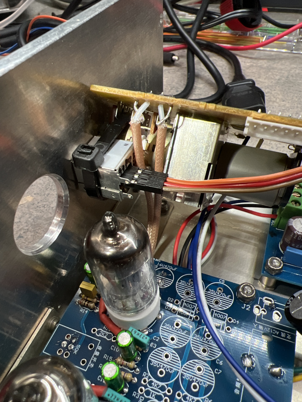
It is alive!
Not the prettiest thing in the world, but it’s working great.
I hadn’t thought out the IR receiver mounting, so a cable tie will have to do.
Nice looking layout, Tom! You really have that small cabinet jam packed to the max! I was wondering what that aluminum angle bracket was going to be used for. I thought maybe that would be used to hold a hum shield to separate the two transformers from the audio PCB and cables. But now I see that you used it to mount three additional circuit boards on edge. Looks cool! So how does it sound?
I've only been able to listen to it for a few minutes, but it sounds fine. I can already say it's really nice to have the remote volume for when quiet songs pop up on my playlists. At some point, I'll have to add some other remote codes to the programming in case the old Sony remote I'm using dies.
I now have LTspice set up and working with the 6J1/5654 tube model. This allows me to tweak schematic values on the fly and run plots to show the effects on output impedance, frequency response, harmonic distortion, etc. The model seems to be giving me very accurate results so far. Here is a screen shot of my modified version of the preamp, showing the rising response below about 30Hz. This is a very good match to what I am actually measuring with my REW setup. Pretty cool. Now I can tweak away without using my soldering iron!!
Using LTspice sims, I discovered what is causing the approximate 1dB rise in the very low frequency response (<30Hz) on my version of the 6J1 preamp. It is the series 0.22uF feedback capacitor (C2m on my schematic). Raising the value up to 0.68uF makes the FR completely flat down to 10Hz. Replacing the 0.22uF with a jumper wire also flattens the FR. I'm guessing, but it seems that the reason the original modifier put this 0.22uF cap in series in the feedback loop was to compensate for the low frequency roll off created by the C9/R13 time constant. He was using a 1uF cap for C9, which resulted in flat low frequency response when used with a 0.22uF series feedback cap. But when I substituted a 3.3uF for C9, this caused the response below 30Hz to start climbing. So I either need to change my C9 cap back to 1uF or I need to boost the value of C2m up to 0.68uF to compensate. I have not had a chance to install this mod yet, but based on what LTspice is showing me, it should work out OK.
Great work and very interesting! If removing C2m gives you flat frequency response, I wonder if it's also doing something else. Could it be preventing oscillation?
I had to use PSpice a lot in college. It was very powerful and very accurate back then but the user interface was painfully hard to learn and use back then. Glad it has a better user interface now. Great when sims match real world measurements.
That is a distinct possibility. Oscillation is very common when you apply negative feedback. I wish we could talk to the original modder and ask him why he put this series cap in the feedback loop. He does not mention why in the video. When I look at most tube amp circuit schematics that use feedback, I generally see a simple resistor or a resistor paralleled with a small value cap in the feedback loop. I have been unable to find an example that uses a small cap in series with the resistor in a feedback loop. My understanding is that this cap is designed to limit the bandwidth of the feedback that is applied to the input, so maybe the circuit will start to motorboat at low frequencies if I remove the series cap. I do not know. I'll run a temporary jumper wire across one of my 0.22uF feedback caps and see what happens.
I was just going to run a single jumper over one of the two 0.22uF caps to take it out of circuit, but, I figured that as long as I had the preamp all taken apart again, I might as well go ahead and mod both channels with two new 100K resistors. Then I could listen to it in stereo to see if I could hear a difference:
Below is an REW graph of the modded frequency response, which now shows a nice smooth roll off below 20Hz, just as LTspice predicted. I took these two measurements using Tom's old Scarlett 2i2 soundcard, so the input impedance is now 10k. One FR measurement shows the response with the 6J1 preamp driving into the 2i2's 10K input impedance using 381pF of cable capacitance. The other measurement shows the response driving into the same 10k input impedance, but this time with 181pF of RCA cable capacitance. Notice the huge difference in high frequency roll off with the higher cable capacitance. This is why it is extremely important to include cable capacitance when measuring a preamp that also has a very high output impedance, in this case about 1K or so. As a result, I decided not to include the recommended 200pF C1m high frequency roll off capacitor at the input to the 6J1 tube. I figured that I could roll off the extreme high frequencies using the RCA cables between the preamp and power amp instead.
Here is the new LTspice model, showing the parts I now have in my preamp. There seems to be a very good agreement between the model and my actual REW measurements. I also listened to the modded preamp with some bass heavy tracks, and there seems to be no tendency to motorboat at low frequencies or squeal unpredicably at higher frequencies due to positive feedback loop problems. Seems very stable. The circuit might still be oscillating at some very high frequencies that I cannot measure or hear, but it seems to sound OK when playing music. I think it is time for me to quit while I am ahead and call this project done!")
I found the interface very easy to learn and picked up on it just a few days. Almost as easy as using the schematic CAD screens within XSim and VituixCAD. The real problem for me, however, was finding and properly setting up the 6J1 tube model within the LTprice program so that it was recognized properly by the program. Each component you place on the schematic is actually a complex submodel of programming code that needs to be properly linked and attached to the system. Lots of trial and error, but I got it working.
That looks excellent. Makes sense to omit the 200pf cap at the input. If there's anything on the inputs above 40KHz, I would think there's a problem in the source or cabling that's feeding the inputs.
I'll have to jumper out my feedback cap and see if anything pops up above the audio spectrum on the scope. My Rigol only goes up to 100MHz and I'm not sure how accurate the FFT is near the upper limit, but it's still worth a quick look.
Bill, Tom,
When you are done, will you post a summary of how to replicate your final build? I might buy one of the kits on Amazon but I definitely don't follow everything in this thread.
Good idea. I will test mine as well. My B&K function generator goes out to 20Mhz and my scope to 50Mhz.
That should be high enough.
Will do. I purchased two of these cheap 6J1 kits and am just finishing up my build of the 2nd one. As I go along, I'm logging my step-by-step procedures and will send you a copy. This 2nd kit build has been very successful so far and uses all the stock parts supplied with the kit, except for the 4 ceramic disc coupling caps. I replaced these with inexpensive WIMA 50V polyester caps from Mouser. For the power supplies, I am using the original +28, 0, -28V voltage B+ circuit with NO changes. I am also using the original 12V heater supply circuit with NO changes. And there is absolutely NO hum. What happened is this: Following plans outlined in a very long diyaudio thread, I cut three circuit board traces with my dremmel tool and then rerouted the power supply ground traces with jumpers. I also cut the on/off switch circuit board traces and jumpered them so that the switch can be placed in a remote location away from signal path traces. With these changes, power supply current does NOT flow through the same input level circuit board ground traces as the signal path ground traces. Result: Zero hum.
Very cool I may even make one...
Another "tubeophile" convert. I think you will really enjoy the warm, full bodied sound of slightly higher 2nd order harmonic distortion. Welcome to the club!")
Everybody is ordering the exact one mentioned in the first post?
https://www.amazon.com/Amplifier-Preamp-Pre-Amplifier-Headphone-Potentiometer/dp/B07LH7JFRF
I got a preassembled device from PE years ago on clearance. I think it only used a single tube. Was something cheap to mess around with but have only pulled It out of the box to inspect.
I have ordered that one and delivery is expired between Jan 30 and Feb 8.