Site Links
Howdy, Stranger!
It looks like you're new here. If you want to get involved, click one of these buttons!
Quick Links
Categories
In this Discussion
Who's Online (0)
Cheap, simple tube linestage

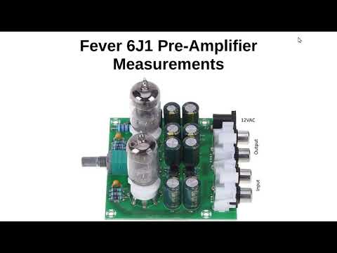
If anyone wants to dip their toe into tubes, here's a cheap kit that uses the same basic circuit as the FX Audio Tube 01.
https://www.amazon.com/Amplifier-Preamp-Pre-Amplifier-Headphone-Potentiometer/dp/B07LH7JFRF
NOS tubes are cheap and plentiful for this one from most vendors.
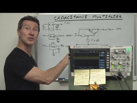
Here's some testing, measurements and cheap mods that really step up the performance.


Comments
Thanks, Tom. Will have to order one of these. I have a bunch of Radio Shack 12VAC xformers that I can use for power.
I just ordered one too. I saw one comment about the heater voltage being up around 18vac even with a standard 12vac supply. Might be able to cobble a 3 pin regulator in there to bring it down if the heater current isn't too high.
Just me but I would ditch that voltage doubler circuit for B+ altogether. The proper sized transformer for that is quite small and cheap. I think his upgrades to film caps, cathode resistor bypass caps, and feedback are totally worth it. In stock form, with a modern SS amp (read low input impedance), it's pretty worthless.
Correct me if I am wrong, but the schematic looks to me like a simple 12.6VDC supply for the heaters. As I see it, the xformer's 12VAC is half-wave rectified with a single diode (D4 1N4007), then dropped to approx 12.6VDC by series resistor R1 (2.2 ohms). The ripple is reduced by smoothing capacitor C13 (680uF). The tubes are connected in series, so each tube would get approx 6.3VDC. Unless I am missing something here. My thinking would be that if the DC heater voltage came out a little high, you could try trimming it down a little by boosting the value and wattage rating of R1. Does that sound right?
I think you are correct, Bill. There are a few of these kits available and I wonder if some are slightly different designs. I'll have to see if I can find which one had that comment about seeing 18v on the heaters.
18v that one reviewer says he measured from that heater supply doesn't make any sense. A half wave rectifier with 12.6vac transformer should be ~5.35vdc. We'll have to see what's really up once the kit arrives.
What is the purpose of this unit? Is it a buffer kind of thing?
It's just a basic linestage preamp. Like Craig said, without the mods it's actually making things much worse. With the mods, it might be a capable little preamp.
My bad. You are correct. This means that the schematic in the video is simply wrong. They either used a full-wave bridge for the heater supply or they hooked the two tube heaters in parallel instead of series. Some of my Radio Shack xformers have centered tapped 12.6 - 0 - 12.6 vac secondaries, so I could wire it up to get a higher starting voltage.
I just got home and my kit was waiting on the front porch. Probing the board shows the heaters are in in series. I just found this schematic that explains the heater voltage. Am I seeing this correctly - they are using part of the B+ voltage doubler to effectively raise the heater voltage?
I just realized they have the Anode load resistors & coupling caps screwed up in the schematic above.
Very interesting! Looks like we are going to get our money's worth on this project! I ordered mine from the link you provided above, so maybe in a few days I will get the same boards and we can compare experiences. I wonder how many more typos are lurking in the schematic, just waiting for us to find them!
I have noticed the floating of the heater voltage with the B+ is a thing. Helps with noise/hum rejection.
Their grounding of C13 doesn't look like what I've seen in guitar amps, but guessing it's for the same reason.
Yes, generally the filament (heater) voltage is raised higher than the cathode voltage. This reduces leakage current between the two that can cause noise/hum. Also indirectly heated tubes (most are) have a maximum filament to cathode voltage. It's something like 100V for an EL34 IIRC.
I found an old thread about this kit on DIYAudio. At least I think it's the same kit they are talking about.
https://www.diyaudio.com/community/threads/6j1-china-preamp-thoughts.309876/
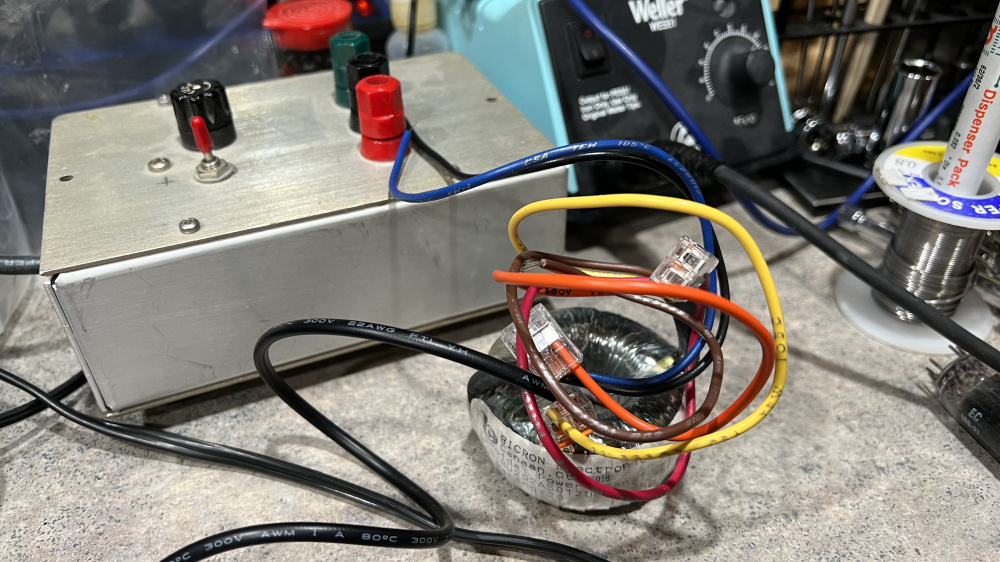
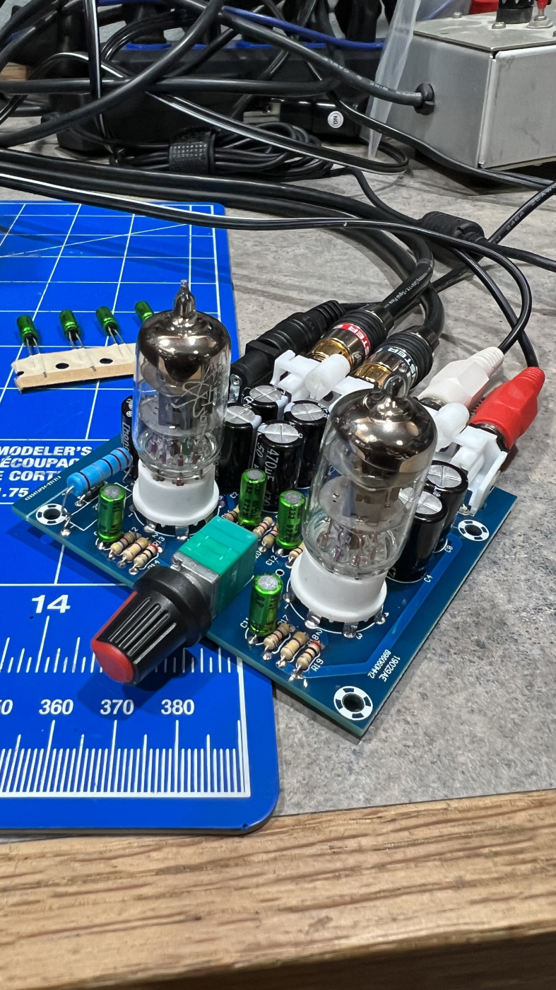
Well I’ll be dipped - it’s alive! I used a spare little toroidal transformer from the parts bin. I have 13.7vac coming in and 6.4v and 6.7v on the heaters. I subbed some Nichicon ES series 3.3uf for the coupling caps in the kit. So far, so good.
I haven’t really even listened to this thing yet, but here are some quick measurements. Frequency response looks great with the 3.3uf caps. The ripples in the low end are from my Focusrite 2i2. It's the Gen1 and that's always been an issue with my unit.
I'm sure this THD measurement isn't lab-grade accurate, but if it's even close, this is surprisingly good for the nearly stock kit.
edit - I guess it's hard see scaled down, but THD is 0.0042% in one channel and 0.0028% in the other.
I haven't understood half of what was said in this thread, the only heater I understand is below. But I do understand "great" and "surprisingly good". Looking forward to seeing where this goes...
You could turn that heater into a cool looking amplifier! Knobs on the top for selector and volume.
Class "A" for its heating potential?
Cool. Nice, clean looking sine waves. I am amazed that the heater voltage is right where it should be. Looking forward to your listening impressions.
As far as I understand it: Gotta get them cathodes toasty so they start spittin electrons, hence the heater. The "grid" is essentially a mesh between the cathode and anode that the voltage signal is connected to in order to control how many of those electrons make it to the anode via charged attraction/repulsion.
I would definitely implement the cathode bypass caps and the feedback circuit to reduce gain and bandwith. That only requires 6 extra small and cheap parts.
I agree - the rest of the mods will be made in the next few days. I also hear a little hum. You can see it on the FFT. I'm guessing it's from from the heater supply, so I'll increase the value of that cap (they shipped this with all 470uf caps) quite a bit and see if that solves the issue. I've also read that others have bypassed the On-Off switch because the traces carrying AC run right beside the input traces to the volume pot.
Good luck with the hum problem. I read through the DIYaudio thread that you posted above and excessive hum seems to be the main complaint of most builders. I don't know if you have measured it, but do you know how much total current the circuit draws from your 13.7vac supply? The higher the current, the greater the ripple.
And voltage doubler circuits make PS noise (ie 60, 120, 180 Hz) twice as bad. That is clearly obvious in your FFT.
Tom, I did some additional research on half-wave rectification on the web and I think both of our original calculations were correct. However, I don't think they are using part of the B+ voltage doubler circuit to raise the heater voltage. The negative terminal of C13 (680uF) is soldered directly to ground on the circuit board. So there is no way that this connection could boost the voltage.
I think what is happening is this: Most of the formula's found on the internet that calculate half-wave rectified power supply voltages do not include the effects of the smoothing capacitor on the resulting average DC output voltage. So, if you start with an AC secondary voltage of 12.6VAC RMS, the peak voltage would be 12.6 x 1.414 or 17.8VAC. Subtracting an approx 0.6V forward voltage drop for the diode would reduce this to 17.2VAC. 17.2/3.1416 = 5.47VDC (approx 5.35VDC as you noted above). However, this 5.47VDC would be the average of the half-wave pulses. When you add a large smoothing capacitor to the circuit, these pulses (or ripple) are smoothed out and the DMM's average voltage measurement increases significantly. The half-wave formula to be used when a large smoothing capacitor is added to the circuit would be [(12.6 x 1.414)- 0.6] x .707 = 12.17VDC.
You are entirely correct! I wonder why the tutorials & calculators I found online don't take this to the next logical step - explaining the contributions of a smoothing cap? I don't think I've ever seen a half wave supply without a cap to smooth it out, but most everything I deal with in vintage SS gear uses a full wave bridge.
Better picture -
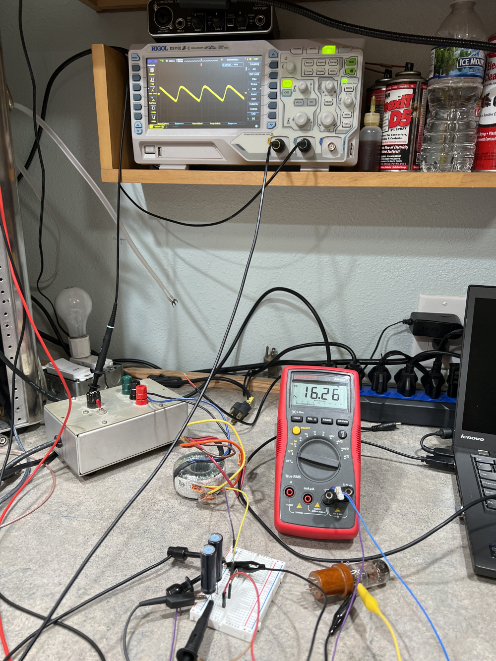
Because I lack any formal electronics education, I had to figure the part about the cap’s contribution out empirically by breadboarding the heater circuit. I was also curious what adding a cap before the resistor might do for the ripple. Drops it down quite a bit - from >600mv to 300mv.
I’m using an old 12at7 as a proxy and the voltage is too high. Instead of dropping more voltage with higher resistance, I’m thinking of adding a 7812 regulator to keep that in line.
I think most of the ripple reduction comes from the capacitors (size and number of stages). If you place a higher resistance between the two capacitor stages, I think the ripple will be reduced substantially. Have you seen this video on ripple reduction?