Craig, not only is this a work of art, but it is also very instructive. You can learn alot about proper layout and lead dressing just by studying this picture.
Yes I would love to build a stereo tube amp some time. The old school point to point circuits get me fizzin. I keep eyeing the ebay kits. But for the moment I'll play with cheap solid state circuits.
Yep, disconnected the while power lead to see if the power supply would stay on. It did stay on but the power supply power-on relay still made a strange sound. The amp board has a couple power indicator leds, both were lit. Maybe not getting the tube seated correctly and the power supply possibly going out were coincidence, probably not, but maybe.
The fan isn't very loud but still audible during quiet passages. Is there an easy peasy way to slow it down? It is 125vac.
Power supply did go poop. 39vdc output from a meanwell se600-48. Voltage range should be from 43-56vdc.
@Kornbread said:
The fan isn't very loud but still audible during quiet passages. Is there an easy peasy way to slow it down? It is 125vac.
Pretty sure most basic ac speed controls are diac+triac based. Very simple circuit unless you just buy a cheap prebuilt one. It messes with the sine wave by chopping out a portion of each cycle so don't know how much emi it generates from the motor.
The DIAC is a diode that conducts electrical current only after its breakover voltage, VBO, has been reached momentarily. Three, four, and five layer structures may be used. Behavior is similar to the voltage breakdown of a triac without a gate terminal.
They are used to hold the voltage at 0 until the breakover voltage (controlled by a pot to make it variable) then the triac switches ON to allow the rest of the sine wave to pass through. This is how it holds power back from the load. a % of the cycle at a time. I think this method maintains a bit of the torque that would otherwise be lost if the amplitude voltage was reduced. Potentially delaying a motor stall until a lower RPM is reached.
@Ed_Perkins said:
The DIAC is a diode that conducts electrical current only after its breakover voltage, VBO, has been reached momentarily. Three, four, and five layer structures may be used. Behavior is similar to the voltage breakdown of a triac without a gate terminal.
Thought this might be of interest to some, PSpice, etc.. Lots of links, although I'm not sure how many dead links are in there. https://normankoren.com/Audio/
Back in 2003, I built the original Pearl phono stage by Wayne Colburn. I made the chassis out of 1/8" thick aluminum panels and angles. No special bending was required. I cut all panels and angles to length on my table saw using a Freud non-ferrous cutting blade. The angles and panels were then drilled and tapped to accept 6-32 brass screws, which, when tightened, held it all together. This layout gave me complete access to the PCB from all directions. The power supply is dual mono with separate transformers for each channel. I used a steel electrical panel box, which sits on the floor. Power (42vdc) is sent up to the phono boards via two short runs of shielded mogami microphone cable.
Comments
I built an amp once, and I totally suck at it. I am jealous of the guys here that can whip up a DIY amp that looks like four figure stuff out there.
Craig, you have to show the underside of that one. It's a work of art under there!
This is the only picture I can find of the underside:
Craig, not only is this a work of art, but it is also very instructive. You can learn alot about proper layout and lead dressing just by studying this picture.
I really like the routered reliefs . . .
Yes I would love to build a stereo tube amp some time. The old school point to point circuits get me fizzin. I keep eyeing the ebay kits. But for the moment I'll play with cheap solid state circuits.
Found a few pics I think Bill took at Iowa 2017
Just died ... Looked for it but couldn't find, did I not post the build on this forum?
So SAD!
Any idea what died?
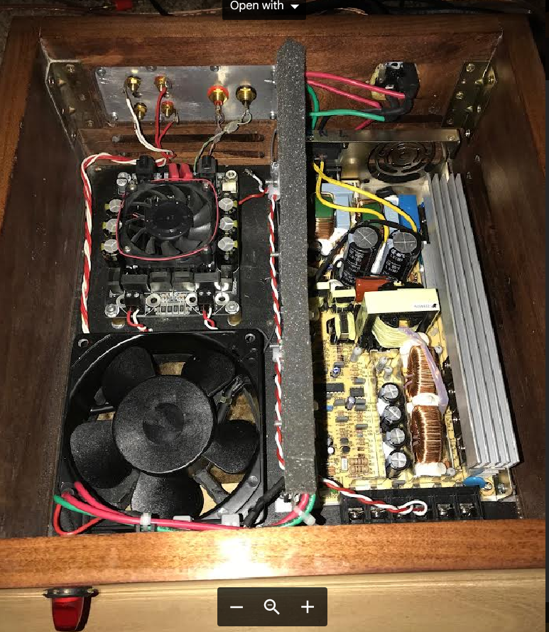
It looks like the white wire coming from the PS is not connected at the amp.
Just saw your post in the Linestage thread - makes sense now.
Yep, disconnected the while power lead to see if the power supply would stay on. It did stay on but the power supply power-on relay still made a strange sound. The amp board has a couple power indicator leds, both were lit. Maybe not getting the tube seated correctly and the power supply possibly going out were coincidence, probably not, but maybe.
The fan isn't very loud but still audible during quiet passages. Is there an easy peasy way to slow it down? It is 125vac.
Power supply did go poop. 39vdc output from a meanwell se600-48. Voltage range should be from 43-56vdc.
Pretty sure most basic ac speed controls are diac+triac based. Very simple circuit unless you just buy a cheap prebuilt one. It messes with the sine wave by chopping out a portion of each cycle so don't know how much emi it generates from the motor.
Diac?
The DIAC is a diode that conducts electrical current only after its breakover voltage, VBO, has been reached momentarily. Three, four, and five layer structures may be used. Behavior is similar to the voltage breakdown of a triac without a gate terminal.
They are used to hold the voltage at 0 until the breakover voltage (controlled by a pot to make it variable) then the triac switches ON to allow the rest of the sine wave to pass through. This is how it holds power back from the load. a % of the cycle at a time. I think this method maintains a bit of the torque that would otherwise be lost if the amplitude voltage was reduced. Potentially delaying a motor stall until a lower RPM is reached.
What did Ed say?
I know what a diac is... just that nobody has used them for decades.
Thought this might be of interest to some, PSpice, etc.. Lots of links, although I'm not sure how many dead links are in there.
https://normankoren.com/Audio/
Nichicon grading. List is from 2016 post#6 https://audiokarma.org/forums/index.php?threads/best-nichicon-series-to-use.732762/

Great information. Thanks!
Back in 2003, I built the original Pearl phono stage by Wayne Colburn. I made the chassis out of 1/8" thick aluminum panels and angles. No special bending was required. I cut all panels and angles to length on my table saw using a Freud non-ferrous cutting blade. The angles and panels were then drilled and tapped to accept 6-32 brass screws, which, when tightened, held it all together. This layout gave me complete access to the PCB from all directions. The power supply is dual mono with separate transformers for each channel. I used a steel electrical panel box, which sits on the floor. Power (42vdc) is sent up to the phono boards via two short runs of shielded mogami microphone cable.
Now that is cool! Looks like something you would pay a pretty penny for in one of the boutique hifi shops.
Someone likes Dale.