Right now on local used market it looks like I can get an analog 2ch oscilloscope along with an old sine/square wave generator for $65. Would those likely get the functionality I'd need to verify basic channel levels and clipping and such? Probably just can't measure distortion. I think I used both analog and digital scopes back in college but haven't touched anything since. Aw man that blue-green glow. Oah the nostalgia!
As long as the scope comes with a good set of probes and both the scope and generator are in good working order, my guess is that these two items would work just fine for basic level and clipping tests. A scope can also be used to spot check frequency response -3dB points and check for any oscillation type problems at high or low frequencies. Square waves can also be used to test for ringing and frequency response problems (but only at very low power levels or you could burn up your amp). I think you could also use you phone, with a good app installed, as the signal generator, but I have not done this.
A scope can also be used to measure visual waveform distortion (just not the percentage or type of distortion). You feed a 1kHz sine wave into one channel of the amp under test and then compare the input and output waveforms on the scope. You scale the output waveform so that it overlaps the input waveform. Any difference in the two waveforms is distortion (assuming the amp is a non-inverting type).
If the scope works, you almost can't go wrong for $65! That's a really old signal generator. You'll probably get lower distortion out of a decent audio interface or dac hooked up to your computer, but it has way more vintage cool factor than a little black box DAC.
One important word of caution when using an oscilloscope to test amps. You are probably aware of this caution, but I think it is worth mentioning. The ground lead of most oscilloscopes is connected to earth ground through the power cord. Therefore, if your amplifier chassis is grounded to the earth and you accidently connect either oscilloscope probe ground clip to a part of the amplifier that is NOT at this same ground potential, sparks will fly. Aways keep this in mind when making scope connections.
Thanks! No, I didn't think about the grounding issue. This prompted me to look further into things. I heard about putting the item being tested on an isolation transformer. Though If the signal ground is isolated from chassis/earth ground that wouldnt realy help.
Lets look at an example. Your chip amp power supply is operating with a dual rail B+ supply of +/- 25vdc (or +25, 0, -25vdc). The zero point between the plus and minus rails is connected to the chassis and the earth through the power cord. This is done for safety reasons and should not be defeated. Note also that the power transformer in your amp is also functioning as an isolation transformer.
Now, if you want to measure the B+ supply voltages of your amp with a battery powered hand-held multi-meter, you would simply connect the positive probe to a +25vdc lug in your amp and then connect the negative probe to the zero lug or chassis. If you wanted to measure the rail-to-rail voltage, you would connect the positive lead to the +25vdc lug and the negative probe to the -25vdc lug on the power supply. The meter would then read approx 50vdc. You can also flip the negative and positive leads of the multi-meter around and connect them backwards and measure -50vdc on your multi-meter.
However, an oscilloscope is not a battery powered device, with floating probes, like a multi-meter. You therefore cannot connect the ground clip(s) of an oscilloscope to either the +25vdc or -25vdc lugs of your power supply to measure voltages in the same way that you can with a multi-meter. Doing so will create a dead short to ground. As a general rule, you must always keep the negative ground clip of your scope connected to something that is at earth ground potential.
This is where I keep getting confused due to getting mixed information.
The secondaries of the transformer are two seperate windings, but I tied a wire from each together into one to essentially create a single center tapped coil (3 wires total). Currently it is left "floating": all the secondary winding wires are only connected to the amp boards, which are insulated from the chassis or other earth grounding. And the transformer has a pair of primaries which are wired in parallel for 110v. Thus only giving a hot and neutral connection. The only ground connection from the transformer being a static shield which would be insulated from all it's other connections. So no, currently nothing from the amp boards is tied in any way to earth ground.
So it sounds like you are saying the "center tap" should be tied to chassis/earth ground? I was getting both yes and no answers when I asked previously. So I was forced to just pick one that seemed least risky to the electronics and run with it.
Drew, My understanding of how to connect two secondaries is to do an unloaded voltage check between each end of each secondary to ground and then use the common lowest voltage leads as the common ground.
I hope this makes sense and that someone more experienced chimes-in here.
Sounds like the confusion might be due to the fact that we are trying to discuss a fairly complicated hookup procedure without referencing a basic power supply and ground return schematic diagram. I think we need to rough up a basic reference diagram of sorts so that we can review all the related connection points a little bit better.
Sometimes schematics can be a bit ambiguous too for grounding IMO so here is a little more literal idea..
Green plate is the amp board with hookup terminals connecting to yellow and black secondary wires. The large circle is the transformer. And the top is terminals of the AC power plug (Hot, Neutral, Ground) with the red, black primary and purple shield wires attached. I haven't incorporated any chassis grounding by this point.
So I add a screw to the chassis to tie the grounds into. If I also tie the center tap wire to this ground while maintaining a connection to the amplifier board center tap connection it should look more like this? (added wires in green)
Rod Elliott does not advocate that the star ground be direct to earth. Ground and Earth should be isolated. He uses a diode bridge in parallel with both a small C and small power R.
My stereo in 1982. DIY 5534 IC preamp a friend of mine designed, B&O turntable, Akai cassette deck and DIY FM tuner built from a surplus tuner board. The shelves were DIY from birch veneered plywood. I still have the shelves.
Later I added a DIY electronic crossover running with Dynaco tube amps. I had a pair of 60 watt mono amps and a stereo 70 built from kits. I had a really early pair of 2 panel Magnepan speakers with DIY 12" subs.
It looks like I added more subs and tweeters.
I know better to do some of the things I did then.
Yes. For a while I had a pair of Mark III's along with a Stereo 70. Looking at used prices I probably should have kept them. I once picked up a Stereo 70 at the local university surplus store for $2. I sold it to a friend who was into tubes.
@Wolf said:
Rod Elliott does not advocate that the star ground be direct to earth. Ground and Earth should be isolated. He uses a diode bridge in parallel with both a small C and small power R.
Ok cool. That pointed me in the right direction. Looks like a beefy bridge rectifier is used so it can handle fault current for a breaker/fuse to do it's job. Then (as far as I can tell) some just leave it at that, or use a 100nf cap and 10r (5w) in parallel with the rectifier. Using one of those panel mount rectifiers would be simple enough to bolt straight to the chassis and p-p wire the resistor and cap right on it.
@4thtry said:
One important word of caution when using an oscilloscope to test amps. You are probably aware of this caution, but I think it is worth mentioning. The ground lead of most oscilloscopes is connected to earth ground through the power cord. Therefore, if your amplifier chassis is grounded to the earth and you accidently connect either oscilloscope probe ground clip to a part of the amplifier that is NOT at this same ground potential, sparks will fly. Aways keep this in mind when making scope connections.
Since I haven't touched a scope for 20 years, I've pretty much forgotten the basics of using them and am going through relearning everything. It seems the practical reality is often times the probe ground strap is not used for earth grounded equipment. IDK if I'm just an idiot for know knowing this lol.. or If I'm saying the quiet part out loud.
Yes I actually just got done watching that vid before posting. I find a ton of info out there on what Not to do, but precocious little on how folks actually take the measurements for real. I suppose it keeps the internet mob at bay, but in the end has limited usefulness when you are coming from a blank slate perspective.
Throw pic of what been using lately, 'the electrocutioner' heh... Call it that as it for me only with how it open and my kids grown, dont anticipate any toddlers running around for another 5+ years. Connex 600w smps (dont buy those cheap 35 buck ones on ebay, they blow up if left on idle). Rod Elliot P101 boards running at about 63v. Had built P101 way back in 2007 with purchased kit then made my own boards that had been sitting around forever, not best quality as they were prototype fab of sorts. Great neutral sounding amp, good horsepower at about 150wpc into 8 (not measure but estimate from build docs).
I purchased the Rod Elliott P101 PCB's and lateral MOSFET's a few years ago but never did anything with them (ie didn't order the rest of the parts). Let me know if anyone is interested. I could be convinced to sell them at or below cost.
Since it has been wet and chilly this week I soldered a bunch of kits together.
Eventually found a little transformer on ali that appears to be spec'd exactly for the high voltage tube pre. So I may get to mess around with it sooner than I thought.
I don't know what your tube preamp circuit requires for a B+ voltage but that transformer looks like a good match for most high voltage tube preamps circuits. If your tubes have 6.3 volt heater filaments then that trans will work good. If they have 12.6 V filaments then it's a no-go. The 200 Vac HV winding full wave rectified should land around 280 Vdc. Add a RCRCRC filter and you could have a very clean B+ in the 200-230 V range. The 20 mA HV rating is more than enough current for most single gain stage circuits.
Also, if you end up really liking how the tube preamp sounds and put it in a nice case, I highly recommend ditching the cheap little pcb mounted volume pot and getting an Alps 10k pot. I think PE still sells them. IME the little pcb pots are not very well balance matched from L to R. The Alps pots are excellent but may cost as much as the Ali tube preamp kit cost
The board calls for 200vac single winding along with the seperate secondary for the heater circuit. There is a zeener diode stack that would appear to limit the voltage to ~250v. The 6j1 tube filaments are in parallel on this circuit. The power supply circuit for the filaments calls for 6-12vac. Regulated back down to 6vdc.
6vac = ~8.4v peak, then subtract the diode drop. That probably hovers around the minimum voltage threshold to properly regulate 6vdc. I wouldn't be surprised if the heatsink is not even needed in that case.
Still waiting on the output caps to ship in. I wanted to try this circuit as a branch from the lower voltage 6j1 project here on the forum. Starting with stock as the baseline. I do have an "ALPS" pot from ali I could try if the stock one is trash. Though, if I'm going to put it in a case, It'd be interesting to replicate it as point to point. Using this circuit as a reference with whatever mods might be found useful. Maybe use a chinese 6z4 to rectify the high voltage. That could render the delay mosfet unneeded and get more glass in the circuit
@Kornbread said:
Would it be cheaper as far as s&h go to order a few of the trans? I'd be in for a few.
I could order some more. Any interest in the board kits too?
Comments
Should be a fun project.
Right now on local used market it looks like I can get an analog 2ch oscilloscope along with an old sine/square wave generator for $65. Would those likely get the functionality I'd need to verify basic channel levels and clipping and such? Probably just can't measure distortion. I think I used both analog and digital scopes back in college but haven't touched anything since. Aw man that blue-green glow. Oah the nostalgia!
Goldstar OS-9020A
BK Precision E310B
As long as the scope comes with a good set of probes and both the scope and generator are in good working order, my guess is that these two items would work just fine for basic level and clipping tests. A scope can also be used to spot check frequency response -3dB points and check for any oscillation type problems at high or low frequencies. Square waves can also be used to test for ringing and frequency response problems (but only at very low power levels or you could burn up your amp). I think you could also use you phone, with a good app installed, as the signal generator, but I have not done this.
A scope can also be used to measure visual waveform distortion (just not the percentage or type of distortion). You feed a 1kHz sine wave into one channel of the amp under test and then compare the input and output waveforms on the scope. You scale the output waveform so that it overlaps the input waveform. Any difference in the two waveforms is distortion (assuming the amp is a non-inverting type).
If the scope works, you almost can't go wrong for $65! That's a really old signal generator. You'll probably get lower distortion out of a decent audio interface or dac hooked up to your computer, but it has way more vintage cool factor than a little black box DAC.
One important word of caution when using an oscilloscope to test amps. You are probably aware of this caution, but I think it is worth mentioning. The ground lead of most oscilloscopes is connected to earth ground through the power cord. Therefore, if your amplifier chassis is grounded to the earth and you accidently connect either oscilloscope probe ground clip to a part of the amplifier that is NOT at this same ground potential, sparks will fly. Aways keep this in mind when making scope connections.
Thanks! No, I didn't think about the grounding issue. This prompted me to look further into things. I heard about putting the item being tested on an isolation transformer. Though If the signal ground is isolated from chassis/earth ground that wouldnt realy help.
Lets look at an example. Your chip amp power supply is operating with a dual rail B+ supply of +/- 25vdc (or +25, 0, -25vdc). The zero point between the plus and minus rails is connected to the chassis and the earth through the power cord. This is done for safety reasons and should not be defeated. Note also that the power transformer in your amp is also functioning as an isolation transformer.
Now, if you want to measure the B+ supply voltages of your amp with a battery powered hand-held multi-meter, you would simply connect the positive probe to a +25vdc lug in your amp and then connect the negative probe to the zero lug or chassis. If you wanted to measure the rail-to-rail voltage, you would connect the positive lead to the +25vdc lug and the negative probe to the -25vdc lug on the power supply. The meter would then read approx 50vdc. You can also flip the negative and positive leads of the multi-meter around and connect them backwards and measure -50vdc on your multi-meter.
However, an oscilloscope is not a battery powered device, with floating probes, like a multi-meter. You therefore cannot connect the ground clip(s) of an oscilloscope to either the +25vdc or -25vdc lugs of your power supply to measure voltages in the same way that you can with a multi-meter. Doing so will create a dead short to ground. As a general rule, you must always keep the negative ground clip of your scope connected to something that is at earth ground potential.
This is where I keep getting confused due to getting mixed information.
The secondaries of the transformer are two seperate windings, but I tied a wire from each together into one to essentially create a single center tapped coil (3 wires total). Currently it is left "floating": all the secondary winding wires are only connected to the amp boards, which are insulated from the chassis or other earth grounding. And the transformer has a pair of primaries which are wired in parallel for 110v. Thus only giving a hot and neutral connection. The only ground connection from the transformer being a static shield which would be insulated from all it's other connections. So no, currently nothing from the amp boards is tied in any way to earth ground.
So it sounds like you are saying the "center tap" should be tied to chassis/earth ground? I was getting both yes and no answers when I asked previously. So I was forced to just pick one that seemed least risky to the electronics and run with it.
Drew, My understanding of how to connect two secondaries is to do an unloaded voltage check between each end of each secondary to ground and then use the common lowest voltage leads as the common ground.
I hope this makes sense and that someone more experienced chimes-in here.
Sounds like the confusion might be due to the fact that we are trying to discuss a fairly complicated hookup procedure without referencing a basic power supply and ground return schematic diagram. I think we need to rough up a basic reference diagram of sorts so that we can review all the related connection points a little bit better.
Sometimes schematics can be a bit ambiguous too for grounding IMO so here is a little more literal idea..
Green plate is the amp board with hookup terminals connecting to yellow and black secondary wires. The large circle is the transformer. And the top is terminals of the AC power plug (Hot, Neutral, Ground) with the red, black primary and purple shield wires attached. I haven't incorporated any chassis grounding by this point.
So I add a screw to the chassis to tie the grounds into. If I also tie the center tap wire to this ground while maintaining a connection to the amplifier board center tap connection it should look more like this? (added wires in green)
Rod Elliott does not advocate that the star ground be direct to earth. Ground and Earth should be isolated. He uses a diode bridge in parallel with both a small C and small power R.
InDIYana Event Website
My stereo in 1982. DIY 5534 IC preamp a friend of mine designed, B&O turntable, Akai cassette deck and DIY FM tuner built from a surplus tuner board. The shelves were DIY from birch veneered plywood. I still have the shelves.
Later I added a DIY electronic crossover running with Dynaco tube amps. I had a pair of 60 watt mono amps and a stereo 70 built from kits. I had a really early pair of 2 panel Magnepan speakers with DIY 12" subs.
It looks like I added more subs and tweeters.
I know better to do some of the things I did then.
Ron
Ditto.
.....sure most would agree.
Is that a Dyna Mark III on the floor?
Yes. For a while I had a pair of Mark III's along with a Stereo 70. Looking at used prices I probably should have kept them. I once picked up a Stereo 70 at the local university surplus store for $2. I sold it to a friend who was into tubes.
$2!! And I though I got a deal on my first ST70.
Ok cool. That pointed me in the right direction. Looks like a beefy bridge rectifier is used so it can handle fault current for a breaker/fuse to do it's job. Then (as far as I can tell) some just leave it at that, or use a 100nf cap and 10r (5w) in parallel with the rectifier. Using one of those panel mount rectifiers would be simple enough to bolt straight to the chassis and p-p wire the resistor and cap right on it.
https://diyaudio.com/community/threads/ground-breaker-isolation.384927/
Since I haven't touched a scope for 20 years, I've pretty much forgotten the basics of using them and am going through relearning everything. It seems the practical reality is often times the probe ground strap is not used for earth grounded equipment. IDK if I'm just an idiot for know knowing this lol.. or If I'm saying the quiet part out loud.
Yes I actually just got done watching that vid before posting. I find a ton of info out there on what Not to do, but precocious little on how folks actually take the measurements for real. I suppose it keeps the internet mob at bay, but in the end has limited usefulness when you are coming from a blank slate perspective.
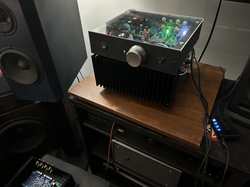
Throw pic of what been using lately, 'the electrocutioner' heh... Call it that as it for me only with how it open and my kids grown, dont anticipate any toddlers running around for another 5+ years. Connex 600w smps (dont buy those cheap 35 buck ones on ebay, they blow up if left on idle). Rod Elliot P101 boards running at about 63v. Had built P101 way back in 2007 with purchased kit then made my own boards that had been sitting around forever, not best quality as they were prototype fab of sorts. Great neutral sounding amp, good horsepower at about 150wpc into 8 (not measure but estimate from build docs).
I tried to hit the awesome multiple times, but it only counts one
I purchased the Rod Elliott P101 PCB's and lateral MOSFET's a few years ago but never did anything with them (ie didn't order the rest of the parts). Let me know if anyone is interested. I could be convinced to sell them at or below cost.
Here is a link to that project page:
https://www.sound-au.com/project101.htm
Since it has been wet and chilly this week I soldered a bunch of kits together.
Eventually found a little transformer on ali that appears to be spec'd exactly for the high voltage tube pre. So I may get to mess around with it sooner than I thought.
https://aliexpress.us/item/3256805754636214.html?spm=a2g0o.order_list.order_list_main.21.131d1802xS3775&gatewayAdapt=glo2usa
I don't know what your tube preamp circuit requires for a B+ voltage but that transformer looks like a good match for most high voltage tube preamps circuits. If your tubes have 6.3 volt heater filaments then that trans will work good. If they have 12.6 V filaments then it's a no-go. The 200 Vac HV winding full wave rectified should land around 280 Vdc. Add a RCRCRC filter and you could have a very clean B+ in the 200-230 V range. The 20 mA HV rating is more than enough current for most single gain stage circuits.
Also, if you end up really liking how the tube preamp sounds and put it in a nice case, I highly recommend ditching the cheap little pcb mounted volume pot and getting an Alps 10k pot. I think PE still sells them. IME the little pcb pots are not very well balance matched from L to R. The Alps pots are excellent but may cost as much as the Ali tube preamp kit cost
@DrewsBrews Would it be cheaper as far as s&h go to order a few of the trans? I'd be in for a few.
https://aliexpress.us/item/3256806251614199.html?spm=a2g0o.order_list.order_list_main.262.21ef1802mfVWlp&gatewayAdapt=glo2usa
The board calls for 200vac single winding along with the seperate secondary for the heater circuit. There is a zeener diode stack that would appear to limit the voltage to ~250v. The 6j1 tube filaments are in parallel on this circuit. The power supply circuit for the filaments calls for 6-12vac. Regulated back down to 6vdc.
6vac = ~8.4v peak, then subtract the diode drop. That probably hovers around the minimum voltage threshold to properly regulate 6vdc. I wouldn't be surprised if the heatsink is not even needed in that case.
Still waiting on the output caps to ship in. I wanted to try this circuit as a branch from the lower voltage 6j1 project here on the forum. Starting with stock as the baseline. I do have an "ALPS" pot from ali I could try if the stock one is trash. Though, if I'm going to put it in a case, It'd be interesting to replicate it as point to point. Using this circuit as a reference with whatever mods might be found useful. Maybe use a chinese 6z4 to rectify the high voltage. That could render the delay mosfet unneeded and get more glass in the circuit")
I could order some more. Any interest in the board kits too?