Site Links
Howdy, Stranger!
It looks like you're new here. If you want to get involved, click one of these buttons!
Quick Links
Categories
In this Discussion
Who's Online (0)
HiVi DIY 3.1 Revisited
It's been a pretty cold winter, which has delayed some planned projects. This situation has presented an opportunity to dig further into the HiVi DIY 3.1's that I picked up shortly before DIY Iowa in 2017 and brought along for a quick demo. My pair painstakingly finished in primer for the show,is shown here.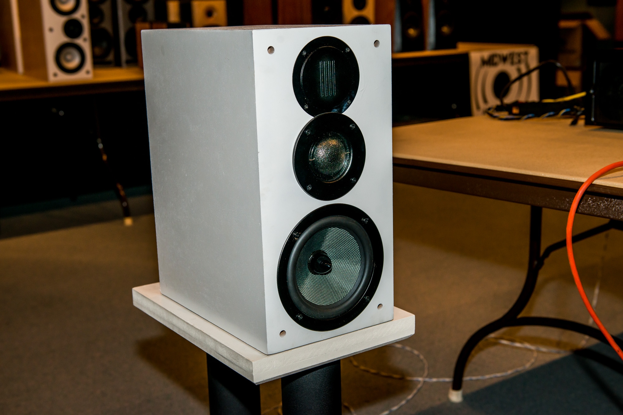 This kit is still available on Amazon for $249/pair including knockdown cabinets with free shipping. Some of the reviews indicate that the overall sound is a bit bright, but can be corrected by increasing mid and tweeter resistor values. Rich (Turn 2) had done this to a pair that he also brought to the Iowa show, but a wiring error led to some strain on the mids - so we stopped the demo early. Rich indicated that he had modified the resistor values.
I wanted to start by measuring the stock FR.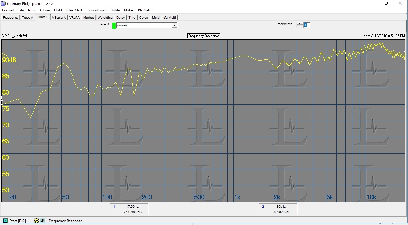 This actually looks almost identical to what is posted on HiVi's website (but using a more revealing scale). I didn't splice in any low frequency nearfield response, so anything below about 200-300 Hz is not accurate. I guess one could call the response 89 +/- 4 dB without really lying - but most of the 8 dB variation is a steady rise from 85 dB in the 200-300 Hz area to 93 dB around 12 kHz. I would expect this to sound a little bright and, to my ears, it does.
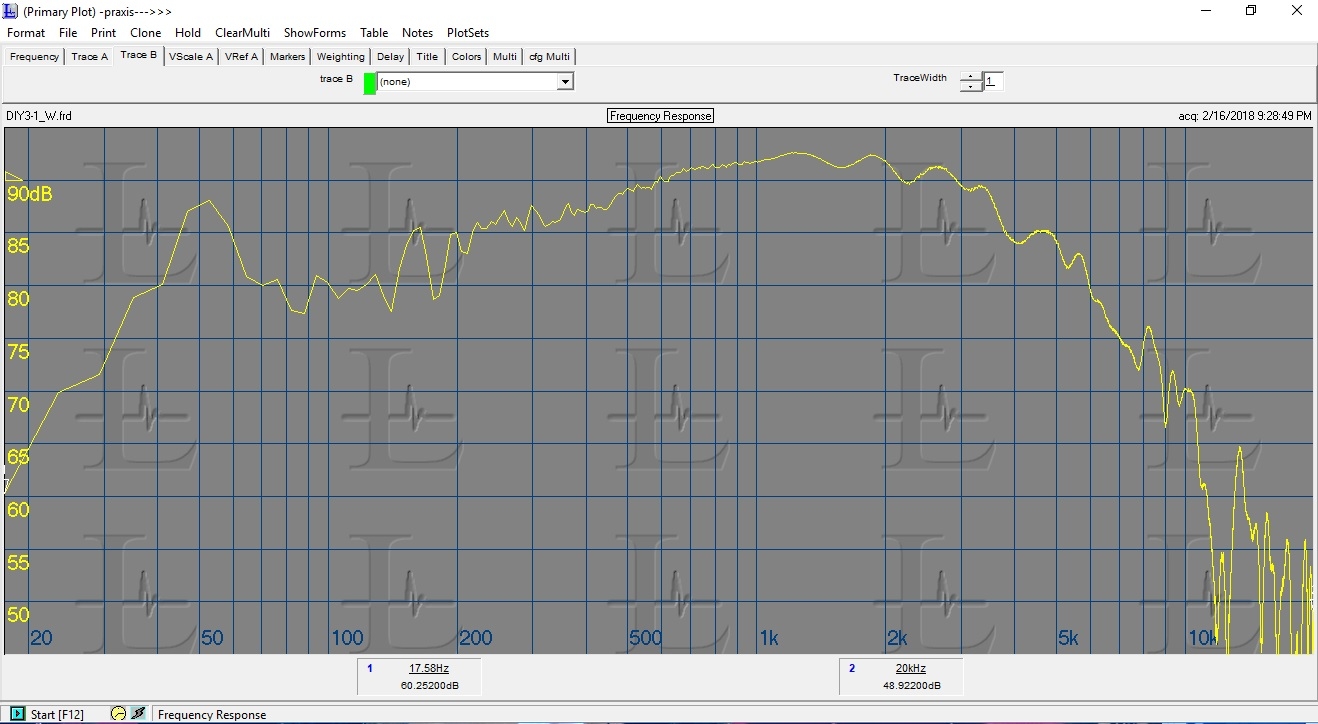
The next step was to unhook the individual drivers from the crossover and see what we are working with. The woofer is the L6-4R (4 ohm), which is the same model number sold by Madisound and Meniscus. The in-box FR is remarkably well behaved with a very smooth rolloff starting between 2 and 3 kHz.
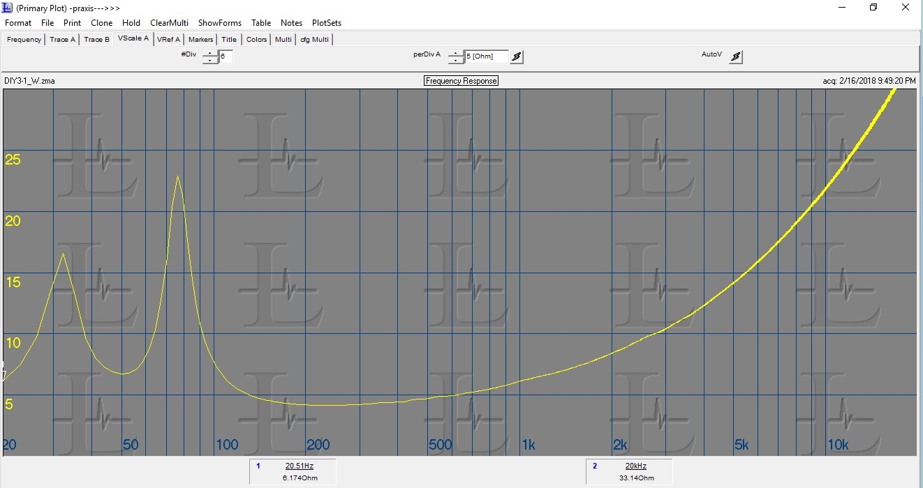
The in box impedance plot shows that the cabinet is tuned to 50 Hz. There is little else remarkable to note.
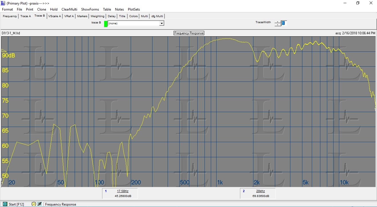
 The midrange is the DMN-B. I used the DMN-A in my recent Indium 7 project and really liked it. Physically the only difference I can readily observe is a 4 screw flange vs. 6 screws for the DMN-A. 6 screws would have limited the overlap between the mid and tweeter flange, so maybe that is the reason. The frequency response is very similar to what I measured for the DMN-A with minor differences likely due to cabinet geometries.
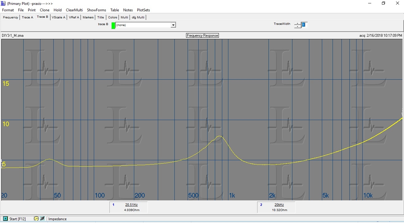
 Impedance is also similar to the DMN-A, including the published Fs of 850 Hz.
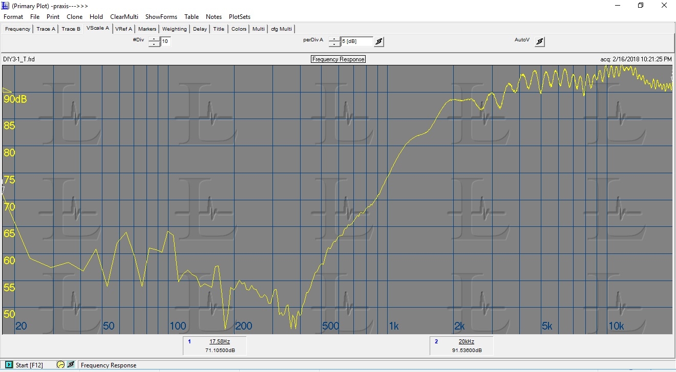
 The tweeter is the RT-1.3B. I have heard the 1.3 before, but have never worked with it. The faceplate is different from the standard RT1.3, presumably to help with the physical overlap between the mid and tweeter flanges. The frequency response is pretty well behaved, which isn't a given for a planar tweeter. There is a slight peak at around 12kHz, which also showed up in the overall speaker response.
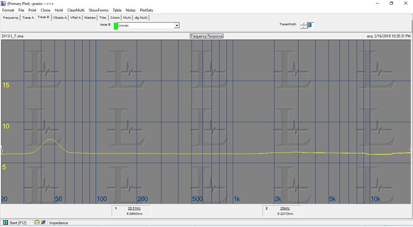
 Impedance is pretty much a flat line at around 6 ohms, as one would expect from this type of tweeter.
  The next step will be to use the measurements to simulate what it would take to balance out the response.
 This kit is still available on Amazon for $249/pair including knockdown cabinets with free shipping. Some of the reviews indicate that the overall sound is a bit bright, but can be corrected by increasing mid and tweeter resistor values. Rich (Turn 2) had done this to a pair that he also brought to the Iowa show, but a wiring error led to some strain on the mids - so we stopped the demo early. Rich indicated that he had modified the resistor values.
I wanted to start by measuring the stock FR.
 This actually looks almost identical to what is posted on HiVi's website (but using a more revealing scale). I didn't splice in any low frequency nearfield response, so anything below about 200-300 Hz is not accurate. I guess one could call the response 89 +/- 4 dB without really lying - but most of the 8 dB variation is a steady rise from 85 dB in the 200-300 Hz area to 93 dB around 12 kHz. I would expect this to sound a little bright and, to my ears, it does.
The next step was to unhook the individual drivers from the crossover and see what we are working with. The woofer is the L6-4R (4 ohm), which is the same model number sold by Madisound and Meniscus. The in-box FR is remarkably well behaved with a very smooth rolloff starting between 2 and 3 kHz.

The in box impedance plot shows that the cabinet is tuned to 50 Hz. There is little else remarkable to note.
 The midrange is the DMN-B. I used the DMN-A in my recent Indium 7 project and really liked it. Physically the only difference I can readily observe is a 4 screw flange vs. 6 screws for the DMN-A. 6 screws would have limited the overlap between the mid and tweeter flange, so maybe that is the reason. The frequency response is very similar to what I measured for the DMN-A with minor differences likely due to cabinet geometries.
 Impedance is also similar to the DMN-A, including the published Fs of 850 Hz.
 The tweeter is the RT-1.3B. I have heard the 1.3 before, but have never worked with it. The faceplate is different from the standard RT1.3, presumably to help with the physical overlap between the mid and tweeter flanges. The frequency response is pretty well behaved, which isn't a given for a planar tweeter. There is a slight peak at around 12kHz, which also showed up in the overall speaker response.
 Impedance is pretty much a flat line at around 6 ohms, as one would expect from this type of tweeter.
  The next step will be to use the measurements to simulate what it would take to balance out the response.


Comments
The first thing to try should be either to adjust the resistor values or try just adding resistors in parallel with the mid and tweeter to pad them down. I will try leaving the stock crossover alone and just adding a resistor across the driver terminals for the mid and tweeter - as this would be a really easy fix. A reasonable first attempt is a 10 ohm resistor across the DMN-B and a 5.6 ohm resistor across the RT-1.3B, which results in a simulated response that would fall into a +/- 2 dB window around an average of about 86.5 dB at 2.83V, 1m.
Sehlin Sound Solutions
If one is starting out assembling these, it might be preferable to change the values of the existing series resistors rather than add parallel resistors. In that case, it looks like a similar amount of padding can be acheived using a 6 ohm resistor on the tweeter and a 3 ohm resistor on the mid.
With this crossover topology, there is another tool that can be used to help with the midrange peak - R3.
Changing R3 from 1 ohm to 2 ohms helps bring the midrange peak down. The value can be increased further. By the time the value gets to 3 ohms, the midrange peak is lower than the 12 kHz peak - which experience tells me won't be desirable. Further padding the 12 kHz peak at that point will shift the overall balance slightly more bass-heavy. I would probably settle on something in the range 2 to 2.5 ohms and call it good.
The real limitation of the stock crossover approach winds up being the shape of the high frequency response. If that could be flattened out, then one could make the tweaks needed to really flatten the rest of the response without the 12 kHz area sticking out as an overall peak and sounding "icy" for lack of a better term.
Here is a modified crossover that would allow reuse of the 3 largest inductors, 2 largest caps, and the PC board itself. The woofer filter is the same as above. The 6.8 uF cap in the midrange filter is changed to 5.6 uF, which addresses the area between 1 and 2 kHz. The tweeter crossover has all new components, but they are small ones...
The result is a much smoother overall response. I've still got some comparing to do, but it appears there are several viable options
1. Keep the stock crossover as is. Add a 5.6 ohm resistor in parallel with the tweeter and a 10 ohm resistor in parallel with the mid.
2. Replace all the resistors. R1=6 ohms, R2=3 ohms, R3=2 to 2.5 ohms.
3. Replace mid and tweeter resistors and the woofer inductor. R1 = 6 ohms, R2 = 2 Ohms, L4 = 2 mH.
4. The perfectionist option. Replace R2 and R3 (both 2 ohms), replace C3 with 5.6 uF. Redo the tweeter circuit (R1=5.6 ohms, C1=1.5 uF, C2=2 uF, L1=1.5 mH).
I will report back with impressions as I work through the options. #1 is quite respectable.
Sehlin Sound Solutions
Sehlin Sound Solutions
L4 from 1.5mH (DCR 0.4 ohms) to 1.5mH (DCR 0.22 ohms)
R2 from 1 ohm to 2 ohms
R1 from 1.5 ohms to 3.0 ohms
Judging from your work mine should still sound a little hot. I know that I've made some improvement and I do have 60-year-old ears,
Maybe the modified DIY 3.1 will become the Indium 5.5 (the Infinity Kappa 6 had a 10" woofer and the Kappa 5 was a two way with the EMIT tweeter)...
That would be a good outcome for me as the modified 3.1's could serve as surrounds for the Indium 7 mains in the man cave.
Sehlin Sound Solutions
Sehlin Sound Solutions
j/k Scott
Sehlin Sound Solutions
Sehlin Sound Solutions
I've run through kind of blue, some gogo penguin, andrew bird's weather systems, they all sound terrific. The Blade Runner 2049 soundtrack is obnoxious, but is a real showcase for highs and lows, it's dark and dramatic and beautiful, and it sounds great on these speakers.
They seem to blend better with the Dayton HF 15" sub than the smaller Echos, but I feel like the soundstage is less broad? Regardless, thanks Marty and Scott for the sage advice! Without the crossover tweaks I'm afraid I would have been disappointed.
I've since built a shopping list from Parts Express for those who aren't familiar with the proper voltage and wattage ratings for the various components, and you can see a finished setup here:
https://imgur.com/JJasE8K
Part numbers and prices in the Reddit thread here:
https://www.reddit.com/r/diyaudio/comments/96brng/help_swan_hivi_31_crossover_circuit_part/
If anyone seeing this doesn't have an account, feel free to ask for help on Reddit.
Davemo: Thank you for posting the original price. I'd buy a few at that price! I'm curious what a front bevel around the tweeter and midrange would do to help the baffle diffraction, and I've also entertained the idea of sticking felt to the front.
I'm glad the mods worked out for you. The shopping list and image of the completed crossover should be helpful for other builders. Thank you for sharing those!
Sehlin Sound Solutions
Right now I'm trying to make friends at the BYU Acoustic Engineering group... Anechoic chamber measurements would be useful for reference and further mods.
https://youtu.be/xBmB6gYZ7Uc
Sehlin Sound Solutions
I will use the foam as well then.
Well I finally finished my HiVi 3.1 perfectionist series, well not exactly, they're still in white primer LOL But they sound much better than I had expected. I used the Foam and I don't think I'm going to mess with them except to finish them off. I mean why get all crazy second guessing everything when its all there out of the box ya know, but do opt for the crossover upgrade, you'll be glad that you did. I've only been running them for about 3 hours but they make me want to listen to music now more so than before. I have a pair of Dayton 10" Sub's that I hooked up to see how that combo would work, and man I have to say that the HiVi's while having a nice low freq punch, the Sub's just filled the gaps with all of that bottom end and I'm really happy with these speakers even more.
I learned a lot for this discussion, and of course I have to thank Scott for his effort's and sharing his findings with us all. Now its time to move on to another project
Enjoy the music fella's