Site Links
Howdy, Stranger!
It looks like you're new here. If you want to get involved, click one of these buttons!
Quick Links
Categories
Who's Online (0)
Volare - A nice, simple two-way design or is it the Catalina "frickin" wine mixer?

My younger son started college this year. As his dorm room lays out, he has a nice location for a flat screen TV and pair of speakers except that it is a relatively shallow ledge along one side of the room. I built the "Hafnium" speakers for him a number of years ago, but those are over 10" deep and rear ported which just doesn't work for his current situation. At fall break, I sent him back with the Rhodiums, but there are shelves full of drivers, so there is no reason this problem can't be solved with something a little more substantial.
One thought I had was something with a similar form factor to the Advent Baby, which was about 16" tall, 11" wide, and 6" deep. Given that these are going on either side of a TV, I also considered something taller and thinner and taught myself enough rudimentary sketch up skills to do a visual comparison.
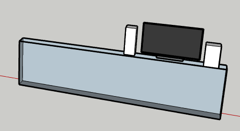
We both preferred the tall, skinny form factor. The next step was to pick some drivers. I have a pair of SB Acoustics SB13PFC25-4 woofers that are happy in about 7 liters tuned to 60 Hz. For tweeters, we have a fair amount of baffle area to work with, so it seemed that something with a full-sized flange would work well aesthetically. I thought about Peerless/Vifa/Tymphany XT25 or DX25 variants, but I also had a pair of Seas 29TFF/W sitting on the shelf as a 5 year old door prize. I haven't seen them used much, so thought this would be a good opportunity.
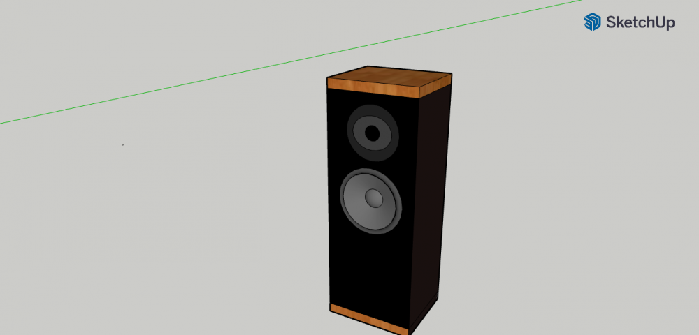
True to the initial Advent Baby, the concept includes black baffle, sides, and rear with woodgrain top and bottom panels. Given the ledge these will occupy, a rear port is probably not an option - so there will be a front port below the woofer. More details to come...


Comments
The sb13pfc is a great driver for the money. I'm sure these will sound great!
I've often wondered about the 29TFF....
InDIYana Event Website
The only project where I've seen the 29TFF used is one of Troel's projects: troelsgravesen.dk/SEAS-CURV.htm.
Drivers are in the box.
I also have some measurements. The manufacturer's data for the 29TFF/W on a quasi-infinite baffle is shown below
My measurements in box correlate reasonably well except for an on axis dip at 3 kHz.
The manufacturer's measurements for the SB13PFC25-4 is shown next
I don't have a 20 degree off axis measurement, but I do have a 15 degree measurement for comparison
The baffle seems to have flattened things out between 350 and 1000 Hz, but now I have a pretty big hump around 1.3 kHz. The fact that these will be placed near a rear wall on a ledge led me to do a front port, so I wonder if that is contributing to the hump. That will require more investigation.
Sehlin Sound Solutions
Tweeter impedance is pretty close to the manufacturer's curve. Fs is a little higher, as is the minimum impedance above Fs. The measured Fs peak is lower than spec.
In-box woofer impedance shows a tuning frequency around the target 60 Hz using the PE 1.5" by 4" flared port. There's a little blip around 350 Hz that may require more investigation. The impedance minimum around 300 Hz and impedance at 20 kHz matches the manufacturer's curve quite well.
Sehlin Sound Solutions
https://c.tenor.com/2Aqj3CAeVrwAAAAM/wine-mixer.gif
They look "Great Scott"
I had a pair of Baby Advents and was thinking of finishing my current tall towers like that. Clean and easy but you beat me to it Doctor Sehlin!
For the Volare, the tops and bottoms are cut from 3/8" thick bamboo cutting boards, which would be something you might expect to see if attending a Catalina Wine Mixer.
Sehlin Sound Solutions
While my son was home over Thanksgiving weekend, I threw together a quick crossover so we could get a feel for what we were dealing with.
This isn't likely to be the final crossover for a couple of reasons.
The woofer circuit doesn't require a lot of extra inductance as the driver has some natural BSC built in (higher output at 200 Hz than 1 kHz on the "infinite baffle". It looks like sensitivity will wind up at 85 dB (2.83V at 1m), which is pretty good for a small two way. The SB13 is not a bass monster, but is both clear and non-fatiguing through the mids. The 29TFF/W has similar qualities.
The plan from here is to do polar measurements for both drivers in order to simulate horizontal polar as well as on-axis response.
Sehlin Sound Solutions
That on-axis tweeter dip at 3kHz really looks strange, as it does not seem to be on the spec sheet curves. Could that be caused by your baffle dimensions or tweeter position?
I took some horizontal polar measurements at tweeter height, 2V and 0.5 meter mic distance, which gives equivalent spl to 2.87V at 1 meter. This is my current standard process for smaller speakers as it allows a little longer gate time than measuring at 1 meter. To get the polars, I used a speaker stand with a rectangular base. On the base next to the floor, I placed a sticker at a position corresponding to the front- and horizontal center of the baffle. I then temporarily marked the path to the microphone and a line representing the horizontal zero degree position of the baffle on the floor. This allowed me to rotate the speaker stand keeping the driver distance to the mic reasonably constant and to measure the angle using a protractor. I measured every 15 degrees from 0 to 180 for each driver. I then fed that information into VituixCAD. This is what I came up with for the initial crossover attempt:
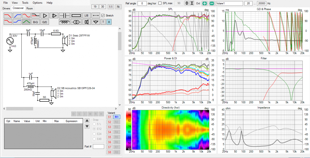
Xsim applies a little smoothing by default (1/24 octave), so the VituixCAD on axis curve is a bit more wiggly. What I have selected to target is relatively flat on-axis and -0.9 db/octave for in-room response (the orange line on the Power & DI chart). Target lines are pink in VituixCAD. It is interesting that the 3 kHz dip is completely gone in the estimated in-room response, which makes me inclined to ignore it. The main issues are the peaks-dips in the 1-2 kHz area, elevated in room response from 2 to about 4.5 kHz, a little peaking at 7 kHz (the woofer has a resonance there, which might not be tamed enough) and a drop in the estimated in-room response vs. the target line above that (29 mm dome in a shallow waveguide is a reasonable explanation, but I will probably let that be what it is as opposed to lifting the on-axis too much).
My son and I thought this sounded pretty good. There were a couple of songs where cymbals were a little "splashy" or balance overall was slightly "bright". I will do some more work to see if some of the measured issues and our listening impression can be improved.
Sehlin Sound Solutions
I've also noticed Seas domes can sound splashy, which was also Jeff's word for them in comparison to the RS28. I think it's mainly due to the motor on the cheaper models.
I've also in the last few years really taken to comping the Fs on a lot of tweeters to reduce the nasal or buzzing qualities they can exhibit. Being that the Fs on these is a bit higher, even at ferro-damped lower magnitude, I wonder what a CL across it could do for you. You'd figure a 29mm dome should have a lower Fs.
You have my interest, keep it up!
InDIYana Event Website
My next step was to add a resistor to the shunt leg of the tweeter network, run the optimizer included with VituixCAD, and make a few more tweaks to help smooth out the estimated room response. I found I could get everything lined up pretty well except for that nasty little peak around 1.3 kHz. Other than that, and the general narrowing of the tweeter axial response above 7 kHz, this is pretty ideal behavior.
This really makes me want to try to attack the 1.3 kHz peak. A notch filter would be an option, but I'm not sure this peak would be reproducible if someone were to build this in, for example, the Denovo 0.23 cu. ft. flat pack - so my next step will be to look at the port behavior a little more closely to see if there is a way to help there.
Sehlin Sound Solutions
I took a nearfield measurement of the port output. There are some pretty strong resonances coming out at 1.2 and 1.5 kHz. Here it is plotted along with the woofer response.
I'm guessing at least one of those peaks is a pipe resonance from the port. I'm aware of a few techniques to deal with this.
I'm already using the Parts Express flared port that is press-in, so I think it will be difficult to integrate a tee into those. I'm curious about the perforated port as it would not take up additional space. Also, if I screw that up too badly, I can still cut off the tube from the flare and fashion a soft port out of foam sheets, or a paper towel roll (which I know from experience works with the PE port I have).
My first attempt was to drill four 1/8" holes at approximately halfway down the port (which is supposed to act on the amplitude peak of primary standing wave). That didn't do as much as I would have liked, so I doubled the number of holes and also added eight holes at about halfway between the first set of holes and the exit (to deal with the next standing wave). It did something....
The yellow curve is the unmodified port, the blue curve has 4 holes near the midpoint of the port, and the teal curve has 8 holes near the midpoint and another 8 holes around the quarter length point. Here is a picture of that attempt...
The paper from Philips that I read about the technique wrapped foam around the outside of the port after the perforations were made. I had a thin sheet of some wool-like damping material, so I tried that for the measurements above. It seemed to do the trick and meet the intent.
To make it easier to take the port in and out for these experiments, I put the terminal cup cutout right behind the port exit. I was a little worried about that creating some issues, so I made a little damping pad for it out of denim insulation and fiberglass window screen...
I will put in the other two screws in after I have hooked up the wires from the terminals.
Let's see if this has any effect on the measured woofer response.
Color coding is the same as the port graph. Yellow is port with no modification. Red has 4 holes at the midpoint. Teal has 8 holes at the midpoint and 8 holes at the quarter point. This might be as good as I can do as the manufacturer's curve (shown in my second post in this thread) has a little peak (looks like a couple of dB) in the same frequency range.
Sehlin Sound Solutions
Did you run impedance sweeps?
If you have the space you might try the solution in the attached pic. It's from a commercial speaker, but can't remember which one. I didn't save the thread info from diyaudio, but the effect on the port resonance was significant enough that I saved the pic for future reference.
Awesome experimentation👍🏻 Bose does something similar on some of their long ports/waveguides. They'll have a small opening of really fine mesh to what I assume is to damp a resonance, as your doing. Nice work!
The initial sweep showed a blip at 375Hz, which would correspond to a wavelength of around 36 inches, so it is almost certainly a standing wave (half wave) due to the internal height of the speaker. I didn't stuff the bottom of the cabinet as I was considering putting the crossover there. I may have to rethink that and did put some Ultratouch in that area for the nearfield port sweeps. For the untreated port case, you can see peaks at around 375 Hz, 750 Hz, and 1.5 kHz, which are all likely due to various modes of the same thing. 750Hz and 1500Hz abberations weren't easily visible on the initial impedance sweep. I will run an "after" impedance sweep, and maybe another if I decide to try to put the crossover in the bottom of the cabinet after all. I'm also curious if my treatment of the port and terminal cup lowered the tuning at all.
Sehlin Sound Solutions
Thanks for posting that one Ed. That is the Technics SB-C700 cross section. That insulation-wrapped section behind the port exit had something to do with my attempted terminal cup treatment. I also noticed that they wrapped the port tube with some sort of fiberfill, so maybe there are perforations in their port too?
Sehlin Sound Solutions
I found the thread, it wasn't diyaudio: https://audiosciencereview.com/forum/index.php?threads/port-resonance-suppression-inspiration-from-technics.13202/. I don't think the Technics port is perforated.
Another alternative to drilling holes in the port is to over-size the port and line it with damping material internally. The damping material will effectively make the port smaller, determining the right length for the intended tuning can become a bit of a struggle as a result.
The little metal mesh pieces under the port.
The diffuser near the end of the port is dividing the air flow into multiple streams that somehow interact and then kill off the resonant peaks. This is what happened with my Zonker alignment. With the OmniMic sweep running continuously, I arranged the internal end of the port to a location that was fairly close to the mouth of my stuffed, internal trap cavity. When I arrived at the correct position, the FR peaking flattened out.
I have everything put together with some Danish Oil on the Bamboo end caps. I also took some final measurements before these head off for some dorm life. Here are a few images, including one that approximates the intended application:
I also took a set of measurements for the completed speaker.
The peak associated with the front port resonance is no longer a major issue in the frequency response measurement, which was taken at 0.5 meter with a 5 msec gate time.
Tuning frequency went up 1-2 Hz - not too bad. There is a small blip around 350 Hz, which I still assume is a cabinet mode.
Estimated in-room response and power response fall off nice and smoothly, as the sim indicated. Dispersion narrows a little more than ideal at high frequencies, but it is a 29mm dome...
The horizontal polar chart shows the same. This chart looks a little different from the sim, as it is normalized - which seems to be how most published charts are shown.
All in all, I am happy with how these turned out. They throw a wide soundstage and did well head-to-head against the Rhodiums, which I consider to be a pretty solid test.
Sehlin Sound Solutions