Site Links
Howdy, Stranger!
It looks like you're new here. If you want to get involved, click one of these buttons!
Quick Links
Categories
In this Discussion
Who's Online (0)
Building an inexpensive 2 channel measurement system

I ordered the parts today for a 2 channel measurement system, so I thought I'd start a new thread to detail my experiences. Will post pics as I go along. Here is what I ordered, all from B & H photo, totalling about $250:
1) Soundworks SoundID mic w/cal file
2) Steinburg UR-22 MKII
3) Neutrik 1/4" TRS stereo panel jacks
4) Neutrik 3-pin XLR plugs
I have everything else I need on hand (small enclosure, spst switches, resistors, banana jacks, mogami mic cable, etc.). I have an i3 HP laptop with Win7 and SE V20 installed. I also have a non-digital 100wpc amplifier ready to go.
And even though I only plan to make FR measurements with SE, I am going to go ahead and construct the complete "Reid's Magic Box of Wonders" exactly as he posted it in the other thread. This will give me a way to double check my DATS V2 measurements as well.
This looks to be a fairly straight forward process of punching or drilling a few panel holes, soldering up a few parts, and making up a few cables. Should be a fun project.
Comments
Glad to see that you're getting on board the 2-channel train, you won't regret it") . I'm surprised you still found a new UR22mkii, it has now been replaced with the UR22c which has a USB-C connection and updated 32bit audio codec.
. I'm surprised you still found a new UR22mkii, it has now been replaced with the UR22c which has a USB-C connection and updated 32bit audio codec.
Once you start using the magic box of wonders you will start to think about selling the DATS, since the jig can do it all. I got rid of my WT3 years ago. It is a pretty simple project to put together, a lazy afternoon and you'll be done.
I'm not fully understanding the XLR plugs, I guess you are building your own mic cable? I recommend using TRS connection between the jig and USB interface so be sure that 48V phantom power is only ever applied to a microphone. In USB audio interfaces, phantom power is on XLR pins only, so TRS connections will never see phantom power whether it is turned on or not. You can of course build them yourself, or buy something off the shelf like this:
https://www.amazon.ca/Hosa-HSS-005X2-Stereo-Interconnect-Cable/dp/B004NCS2SS/ref=sr_1_5?crid=2EPZQIA7CCVVD&keywords=hosa+trs&qid=1640899849&sprefix=hosa+trs+,aps,153&sr=8-5
Mono "TS" cables are fine too, but I use the TRS just for flexibility in case I want to use it for something else.
Not that it matters but "Digital" amps are fine btw, but it is crucial to not use BTL (bridged) amps, like you will find in most low cost class-D "chip amp" products. With a true 2-channel measurement like ARTA, the frequency response of the amp and anything before the reference (the jig input in this case) is compensated for, since the measurement is normalized to the reference signal. REW at least today only allows for reference to be used as timing reference, but not a true 2-channel measurement. I'm really not sure why REW doesn't do it, it's a fairly simple feature to implement IMO.
I look forward to this thread and hope you provide all the details. I bought the Steinberg UR-22 MKII and dcibel's old Dayton EMM-6 and hope to get a measurement system up and running by February, but I'm definitely intimidated.
Intimidated of building the jig, or the whole process?
You shouldn't be intimidated, the jig is really no more difficult to build than any basic crossover, and if you get an ARTA license, without getting into all the "advanced" features of ARTA, simply creating measurement data for use with VituixCAD is incredibly easy, it should be about as easy as a measurement process can be, even simpler than if you were to use a "plug and play" USB mic.
What is the benefit of a 2 channel measuring system?
All the cool kids are doing it")
Main benefit - Accurate timing information between multiple measurements without any fussing around.
Secondary benefit - Compensation for non-linearity of all signal prior to the "reference" channel input. One benefit here is the ability to add a protection capacitor to the signal chain without affecting the measured frequency response.
Third benefit - 2 channel jig doubles as impedance measurement for T/S and R/L/C measurements.
OK, now I get it. You just saved me from a major screw up. I was going to make my own microphone cables with a 1/4" stereo TRS connector for the jig's connection end and a 3-pin XLR connector on the Steinberg's end. I didn't realize that the Steinberg's xlr input jack is a dual purpose type that will accept either a 1/4" stereo or mono TRS type plug OR a standard 3-pin XLR microphone plug. So when I make up the cables, I want to put a 1/4" stereo TRS plug on both ends. Or I could put a 1/4" mono TRS plug on both ends.
Yep, brand new and in stock. The UR22c was about 15% more and on back order.
Yes. The connection of the mic is basically to disconnect the impedance probe from the UR22 and plug in the mic instead, switch the jig to "SPL". You will find that all "pro audio" interfaces include dual input connectors that accept either XLR or TRS, so you are not limited and can connect either your guitar or mic to any input.
The jig could be expanded to include an XLR connection for the mic, and then the impedance/spl switch becomes a 2-pole switch to bypass the resistor as well as switch from the impedance to mic input probe. This is what is detailed in the ARTA jig application note, and allows the equipment to remain always connected regardless of the operation. I went for a simplified approach, where you simply inplug one and plug in the other to change from impedance to SPL measurements.
Intimidated just connecting the mic, mkii, laptop... Calibrating... What is 48v phantom power, etc. USB mic with REW was awfully easy . I've looked at the VituixCAD instructions and think it will be okay once I really get started, but just seeing it on paper isn't all obvious to me.
I haven't looked at the jig and was going to just use REW (I have a pretty new DATS v3) but will now look at the jig and the benefits. I'm open to ARTA if it's better or even just easier.
I'm not a big fan of REW user interface, so I prefer ARTA which is more purpose built for speaker design, but it is a added USD$100 expense for a licence to save your measurements in ARTA, which is of great benefit to VituixCAD as it can process all measurements in bulk making the process quite streamlined. VituixCAD can process REW measurements in bulk as well, but I may be less helpful there as I'm not very experienced with it.
I'll be sure to post detailed pics as I wire up and solder all the switches, jacks, and resistors. Will also post detailed pics of the microphone cable assemblies, showing how they are soldered up at each end and how they connect to the jig and ur22. Will also show my grounding scheme, showing where the jig metal chassis is connected to signal ground. Should be a fun project.
Generally the "shell" of the TRS jack is already going to connect to the chassis so it is grounded by design. In retrospect that may not be the best idea for such a jig, if an electrical fault were to occur you'd probably end up shorting out your amp.
Here's the bar to beat for assembly quality, good luck and have fun!")
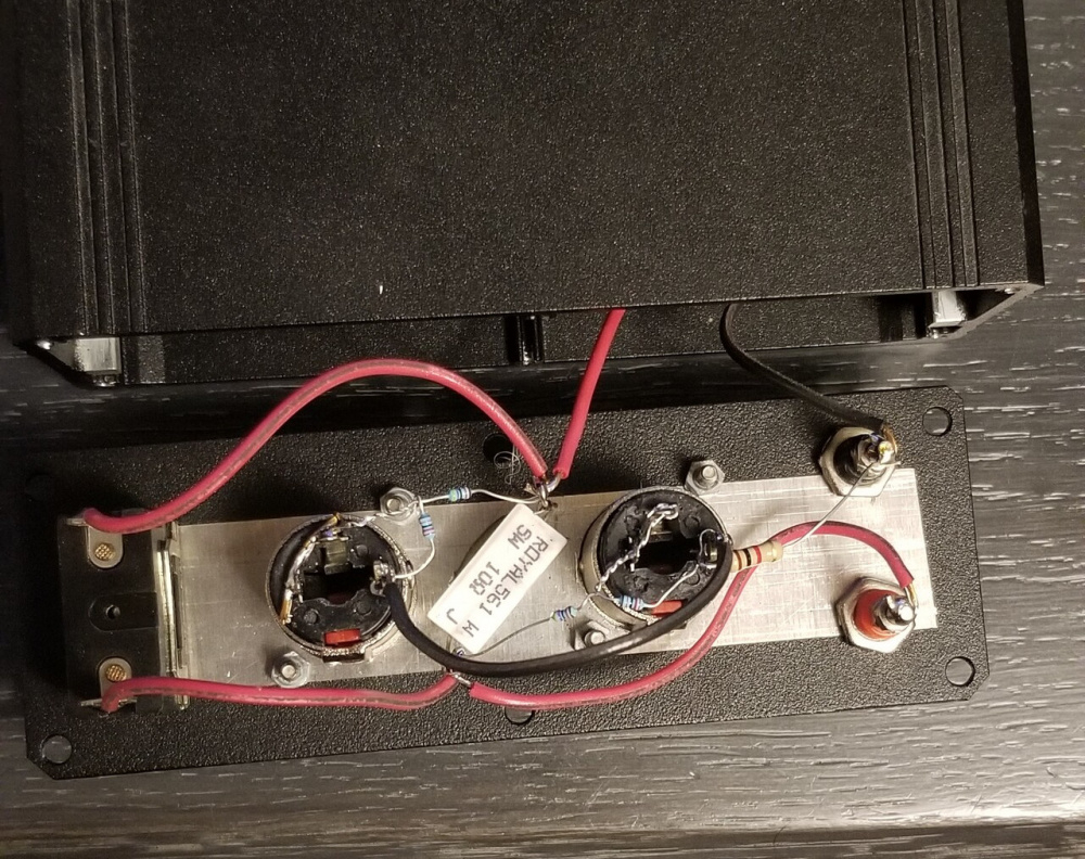
Thanks for the pic. Looks like a very simple and straightforward set of connections. The red and black wire going into the enclosure would then simply connect to the rear panel set of banana jacks and your done! I will also be adding the optional SPST switch and 47uF cap next to the other switch. My enclosure's front panel is 1 15/16 x 8 1/4 (49x210mm), so I will have plenty of room to add another switch.
Here is a copy of dcibel's schematic, just in case anyone is having trouble finding it in the "jigs, gizmos, and useful stuff" thread:
Late night brain problems..,the TRS casing is on the line level side of the resistors, and doesn't present a short circuit hazard for the amp, at worst you have 1kohm across the amp.
While I am waiting for the microphone and soundcard to arrive, I decided to gather up the parts that I already have on hand and start building the enclosure.
I found on old Radio Shack steel cabinet, #270-272A that I bought roughly 25 years ago. I had never opened it, as the project that it was purchased for never got off the ground:
I printed some full scale drilling templates for the front and back panels:
I taped one to the back panel:
And I taped one to the front panel:
Then I drilled all the smaller holes on my drill press. I happened to have one Neutrik 1/4" TRS jack on hand, so I used it for sizing the bigger two holes needed for these jacks. They were too big to drill, so I used my 7/8" diameter Greenlee chassis punch:
The 7/8" hole was just a little too small for the Neutrik jack, so I widened the hole just slightly with a half round file:
Mounted all the jacks and switches today except for the one that I am still missing. I'm about half way there, still have to install the black ground signal wiring and the parts that attach to the Neutrik jacks. Fed Ex tracking says the package will be delivered on Sunday by 4pm. I thought this was a typo, but when I checked, apparently Fed ex now has a Sunday home delivery service.
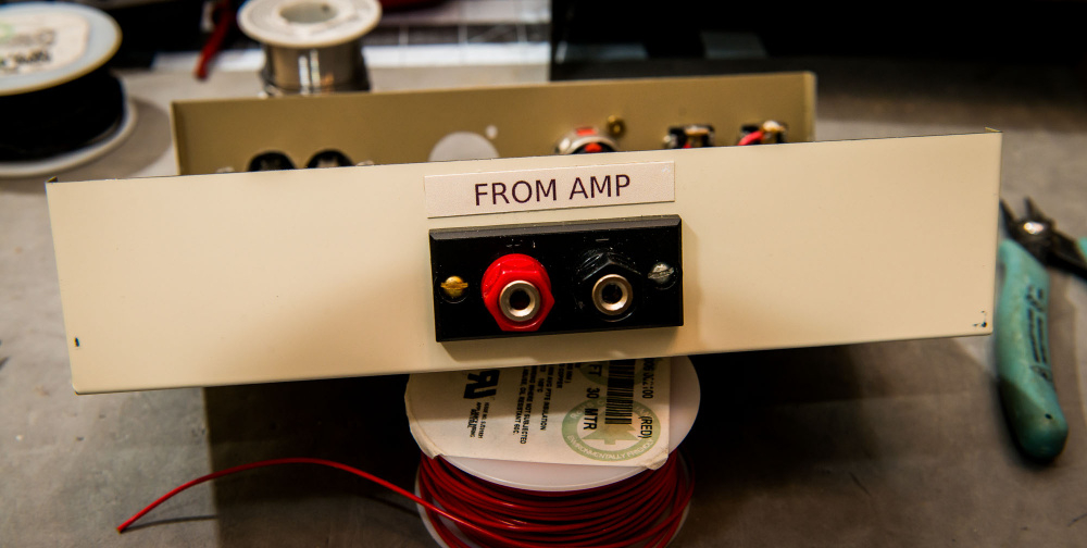
Still waiting for parts. In the meantime, I printed labels and glued them on with double stick carpet tape. I printed the background color so that the text blended in. Seems to look OK.
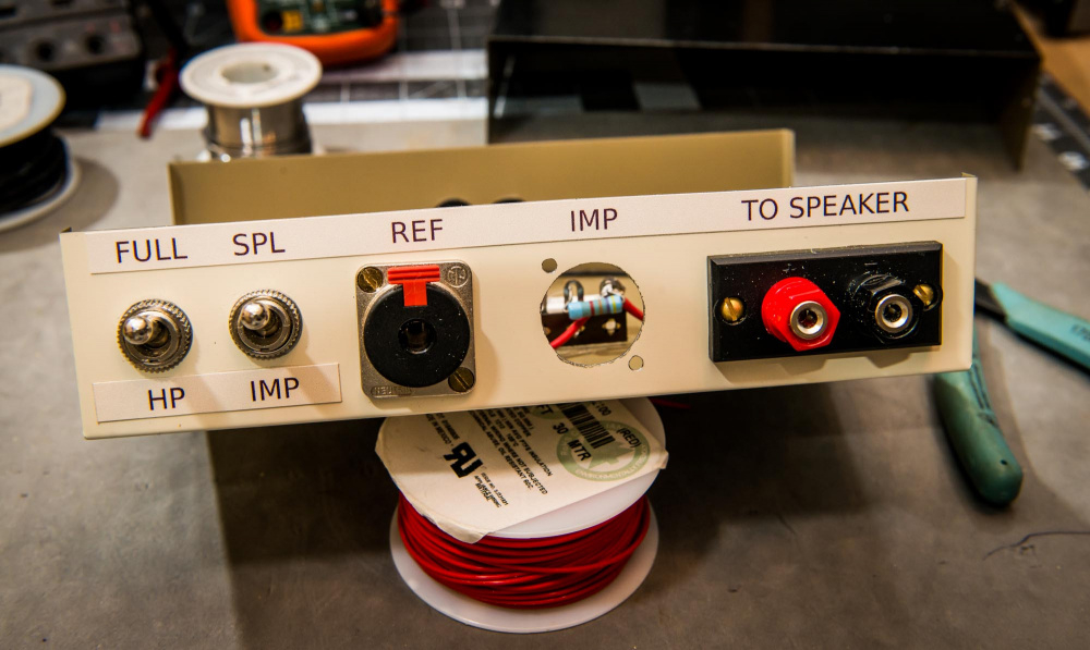
What do you think?
Couple more wires and a resistor added. That's about as far as I can go for now. My Fed Ex shipment was delayed.
It looks lovely.
Yup, El Professional
That case is probably large enough to build in a small amp. Lol
Ya, plenty of empty space. I was thinking of gluing a heavy piece of floor tile toward the back. That way, the enclosure would not slide around as much when I insert or remove the TRS cables!")
Not the worst idea, I once had a piece of late 90's video hardware from Silicon Graphics that had a 1/8" steel plate for the base for the sole purpose of giving it weight for the same reason, and so that it would still sit flat on a table with two bulky video cables plugged in the back.
Keep in mind though that those TRS jacks are "locking" so removing them will be a two handed operation anyway.
If decibel we're ok with it would people be interested in a pre-made circuit board?
I've been looking for an easy circuit board job and this looks like a good candidate.
Knock yourself out, but I personally don't think something this simple needs a PCB. If I were to go to the trouble of designing a PCB, I'd go all out with a full featured solution like what is in the ARTA jig app note:
https://artalabs.hr/AppNotes/AN1-MeasuringBox-Ver2-Rev3Eng.pdf
That jig already has a PCB designed, see the appendix on page 11. Can be purchased from a German site. The PCB there also uses RCA connectors, yuck. I would redesign it for TRS connections, and XLR for the mic, and some minor modifications to the circuit to make it more suitable for a USB interface with mic pre-amp built in, but it would include the mic connection and cal switch right on the jig.
Ken, good luck if you decide to design a PCB. Switchcraft makes a variety of right angle type, PCB mount, XLR and TRS jacks that you could use for this. I basically decided to go with point-to-point because I have alot of experience with this "old skool" method. Terminal strips work well to securely hold a small number of parts in position as you solder and wire things up.
I've got some basic questions. My mic is XLR, Dayton EMM-6 (calibrated through CSA). My sound card is the Behringer UMC22 https://www.behringer.com/product.html?modelCode=P0AUX
Looks like I need a separate 48v phantom power amp for the impedance measurements?
I assume for FR measurements nothing else is required if I use the ARTA switch box.
No, you don’t need 48v phantom power for impedance measurements, 48v is the power for the condenser mic. You’ll find the switch on the back of your UMC22.
The problem you’ll have with the UR22 is the “instrument in” which is not a line input, but high impedance 1Mohm input for connecting your guitar directly. You may try recalculating resistor values for that input at 1Mohm input impedance, but I’d recommend getting UMC202 or UMC204 for a cheap Behringer option. It makes much more sense for both inputs to be the same as they’re being directly compared with every measurement.
OK. My bad. The ARTA Switch Box PDF is using RCAs for the mic connection. Looks like I would be better off skipping the switch box and going to figure 6 and 7 separate connection setups.
I had a similar M-Audio USB sound card that I used in a single channel ARTA measurement system. My recollection was that the second channel setup was used to set the timing of the impulse response.
Figure 7 is exactly what is happening here... with provisions for impedance measurement as well using a power amp, not direct from the soundcard output as shown in figure 6. If you RTFM for ARTA and LIMP you'll find these diagrams which is what is being built here:
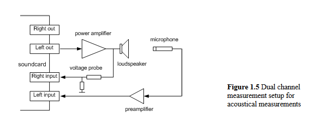
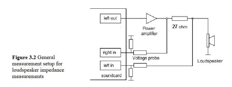
Benefits of the 2-channel measurement are at the top of the thread, see my response to Billet's question. Accurate and reliable timing information is a huge benefit for loudspeaker design, you can effectively forget about multiple measurements to determine acoustic delays and the other limitations of keeping the mic stationary at tweeter axis. The 2-channel response compensation by normalizing the measured response to the reference is hugely beneficial as well, for example including a protection cap can have no influence on the measured response, at least down to the point where the signal gets buried in the noise floor. Apart from speaker T/S parameters and impedance, you will also have the ability to measure transfer functions of passive and active filters, DSP output, etc.
You can think of this system as the poor man's Clio, as the Clio system is essentially this, USB interface and jig built into a single box with measurement mic. The smaller/cheaper Clio pocket is a single channel system