Ok, I'm stupid. Explain how this Holy speaker is supposed to work.
Sound comes out of the big hole in the middle 😁. Seriously though, Ken is right. I thought this would be cool for a number of reasons and now I'm going to try to make it sound good.
A comment on PETT said he should put the tweeter in the side and face the narrow edge forward. I'm sure the omni/bipolar equation would still come into play.
Question? What if the drivers were Coax with tweeters?
That would achieve the completely open look I was going for and I think it wouldn't even sound that bad. There's so much chaos in the sound propagation, that I'm not even hearing the distinct peaks and dips that I can measure at a point in space and I suspect that would be the case with multiple HF drivers as well. Part of the issue when I do stuff like this though, is that I don't want to spend a bunch of cash on something that has a high probability that I'll never listen to it after I build it, so I'm not sure if I'd spring for 16 coaxial drivers.
I got a chance to mess around with a tweeter (sitting on top of cab) and some xo parts today. Taking out the 400Hz peak helped a ton with the balance and I think this is going to work out pretty well. Ironically, my biggest issue right now is some bass/midbass bloat whose origin is not obvious.
@jhollander said:
Dan I heard you gave up on this design?
I haven't 100% given up yet, but I hit a roadblock that is enough to put it on a potentially permanent back burner. These damn things have the nastiest standing wave I've ever encountered, creating an impedance peak almost as tall as the woofer Fs peak and that odd response that peaks at 400Hz and slopes down quickly on either side. It was already going to take some work in the crossover just due to the format, but the audible peak was just too much to deal with. I've talked with some of you guys about some potential solutions, but I've got too many other priorities to struggle with this one.
With that said, any of you guys that want to pick up where I left off can have the cabs and parts. I'd love to see this concept seen through and I've honestly done the hard part (the CAD/3D printing for the woofer ring). Both cabs are built out for the woofers, but I hadn't worked out the details of the tweeter mounting strategy yet.
@jhollander said:
So is 400 Hz related to the diameter?
I think so and honesly I was expecting something like that, basically an exaggerated beaming situation with no central propagation source to dilute the extremes. I compensated for that with an LCR filter but the standing wave - I think it was at 175Hz, but I'd have to measure again to be sure - added a whole other element to deal with. I really wanted to make it a passive speaker, but if nobody wants to tackle it, I'll probably (eventually) pack the bottom with fiberglass to kill the standing wave and beat it into submission with a MiniDSP.
I think so and honesly I was expecting something like that, basically an exaggerated beaming situation with no central propagation source to dilute the extremes. I compensated for that with an LCR filter but the standing wave - I think it was at 175Hz, but I'd have to measure again to be sure - added a whole other element to deal with. I really wanted to make it a passive speaker, but if nobody wants to tackle it, I'll probably (eventually) pack the bottom with fiberglass to kill the standing wave and beat it into submission with a MiniDSP.
I think so and honesly I was expecting something like that, basically an exaggerated beaming situation with no central propagation source to dilute the extremes. I compensated for that with an LCR filter but the standing wave - I think it was at 175Hz, but I'd have to measure again to be sure - added a whole other element to deal with. I really wanted to make it a passive speaker, but if nobody wants to tackle it, I'll probably (eventually) pack the bottom with fiberglass to kill the standing wave and beat it into submission with a MiniDSP.
How do you find/measure the standing wave?
There's a huge impedance peak at 175Hz, which corresponds with a 38.5" half wavelength, the internal height of the speaker. I've never made a speaker this shape before - the other internal dimensions are 16.5" wide and 5" deep. I didn't think any of that was too outrageous and I thought the big hole on one end would break up some of the length. I was wrong. It's bad. I didn't save the measurement and I have the speaker tucked away, but next time I pull it out, I'll try to remember to take a quick measurement and post it here.
A curse on you, Herr Doktor Hermann von Helmholtz!
I imagine the cabinets are already glued up and the interior is no longer accessible, so turning the thing in to some kind of transmission line might be out of the question.
Man, I would love to take a crack at these, but I wouldn't have time for a while. This was a really interesting concept, that needs to be hammered into something at least listenable, if not great.
@ugly_woofer said:
Man, I would love to take a crack at these, but I wouldn't have time for a while. This was a really interesting concept, that needs to be hammered into something at least listenable, if not great.
Most of you know that I took over this project from Dan. I've been slowly working on these and finally shot some color on them. I currently have one polished out.
Ha, I wasn't thinking about that, I was trying to get the stupid camera to show the color more accurately. They're far too red in the first two photos. Photography is not my Forte.
Comments
InDIYana Event Website
Another thought would be to do the edge-lighting like in the cool black-mirror effects.
InDIYana Event Website
InDIYana Event Website
I got a chance to mess around with a tweeter (sitting on top of cab) and some xo parts today. Taking out the 400Hz peak helped a ton with the balance and I think this is going to work out pretty well. Ironically, my biggest issue right now is some bass/midbass bloat whose origin is not obvious.
InDIYana Event Website
Dan I heard you gave up on this design?
I haven't 100% given up yet, but I hit a roadblock that is enough to put it on a potentially permanent back burner. These damn things have the nastiest standing wave I've ever encountered, creating an impedance peak almost as tall as the woofer Fs peak and that odd response that peaks at 400Hz and slopes down quickly on either side. It was already going to take some work in the crossover just due to the format, but the audible peak was just too much to deal with. I've talked with some of you guys about some potential solutions, but I've got too many other priorities to struggle with this one.
With that said, any of you guys that want to pick up where I left off can have the cabs and parts. I'd love to see this concept seen through and I've honestly done the hard part (the CAD/3D printing for the woofer ring). Both cabs are built out for the woofers, but I hadn't worked out the details of the tweeter mounting strategy yet.
So is 400 Hz related to the diameter?
I think so and honesly I was expecting something like that, basically an exaggerated beaming situation with no central propagation source to dilute the extremes. I compensated for that with an LCR filter but the standing wave - I think it was at 175Hz, but I'd have to measure again to be sure - added a whole other element to deal with. I really wanted to make it a passive speaker, but if nobody wants to tackle it, I'll probably (eventually) pack the bottom with fiberglass to kill the standing wave and beat it into submission with a MiniDSP.
The impedance peak is what I find interesting. I have some have baked plans for a round speaker. I need to think about how to avoid this.
How would you model different shapes and/or materials near the middle, or protruding from behind?
How do you find/measure the standing wave?
There's a huge impedance peak at 175Hz, which corresponds with a 38.5" half wavelength, the internal height of the speaker. I've never made a speaker this shape before - the other internal dimensions are 16.5" wide and 5" deep. I didn't think any of that was too outrageous and I thought the big hole on one end would break up some of the length. I was wrong. It's bad. I didn't save the measurement and I have the speaker tucked away, but next time I pull it out, I'll try to remember to take a quick measurement and post it here.
A curse on you, Herr Doktor Hermann von Helmholtz!
I imagine the cabinets are already glued up and the interior is no longer accessible, so turning the thing in to some kind of transmission line might be out of the question.
Man, I would love to take a crack at these, but I wouldn't have time for a while. This was a really interesting concept, that needs to be hammered into something at least listenable, if not great.
Something as simple as drilling a bunch of holes on the bottom and then stuffing the shit out of the cabinet might be sufficient.
I suggested cutting off the bottom and wedging pink foam "V" in under the orifice to see if it helped, and yield a mltl type of construction path.
InDIYana Event Website
Let me know when you're ready....
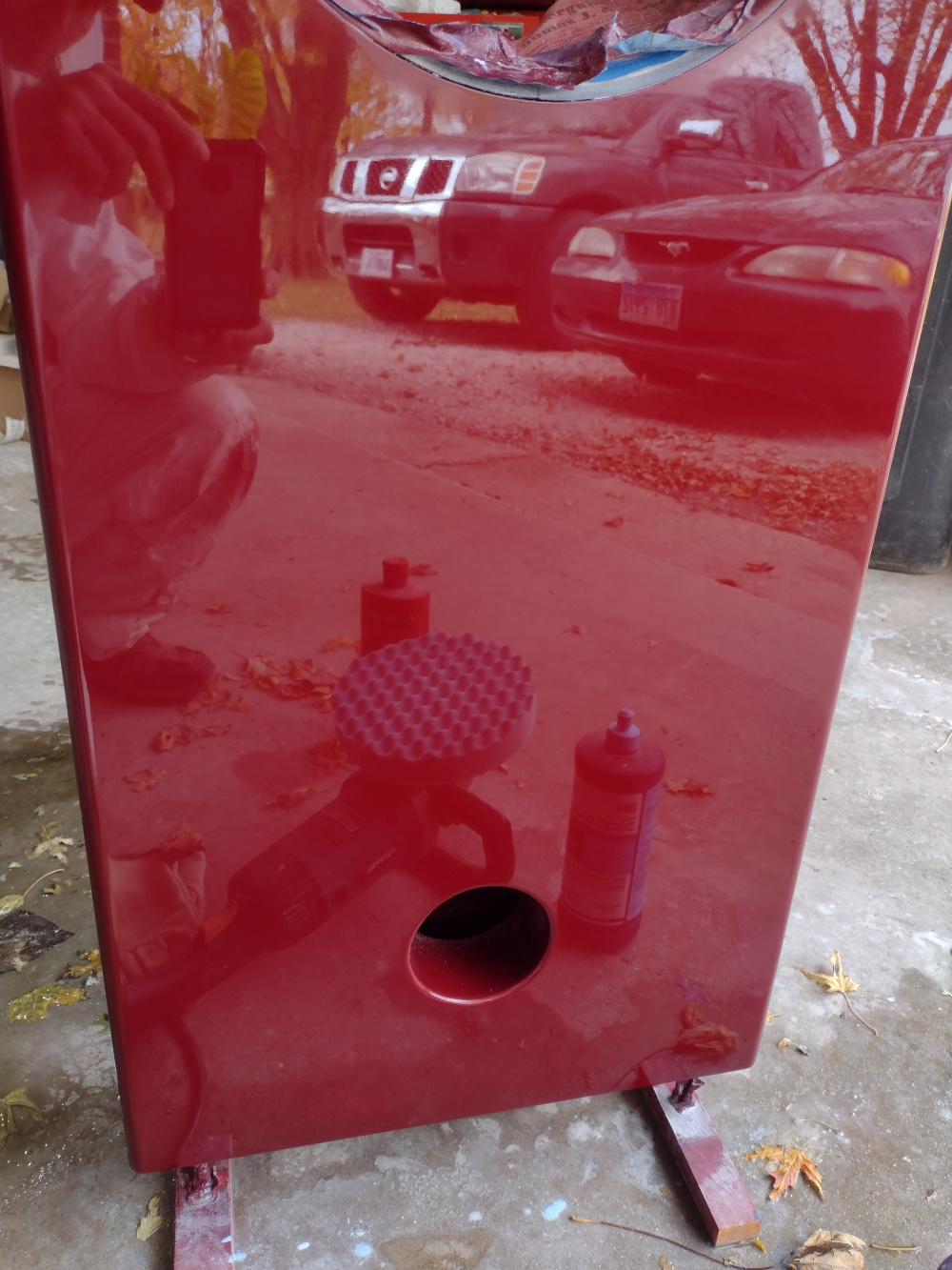
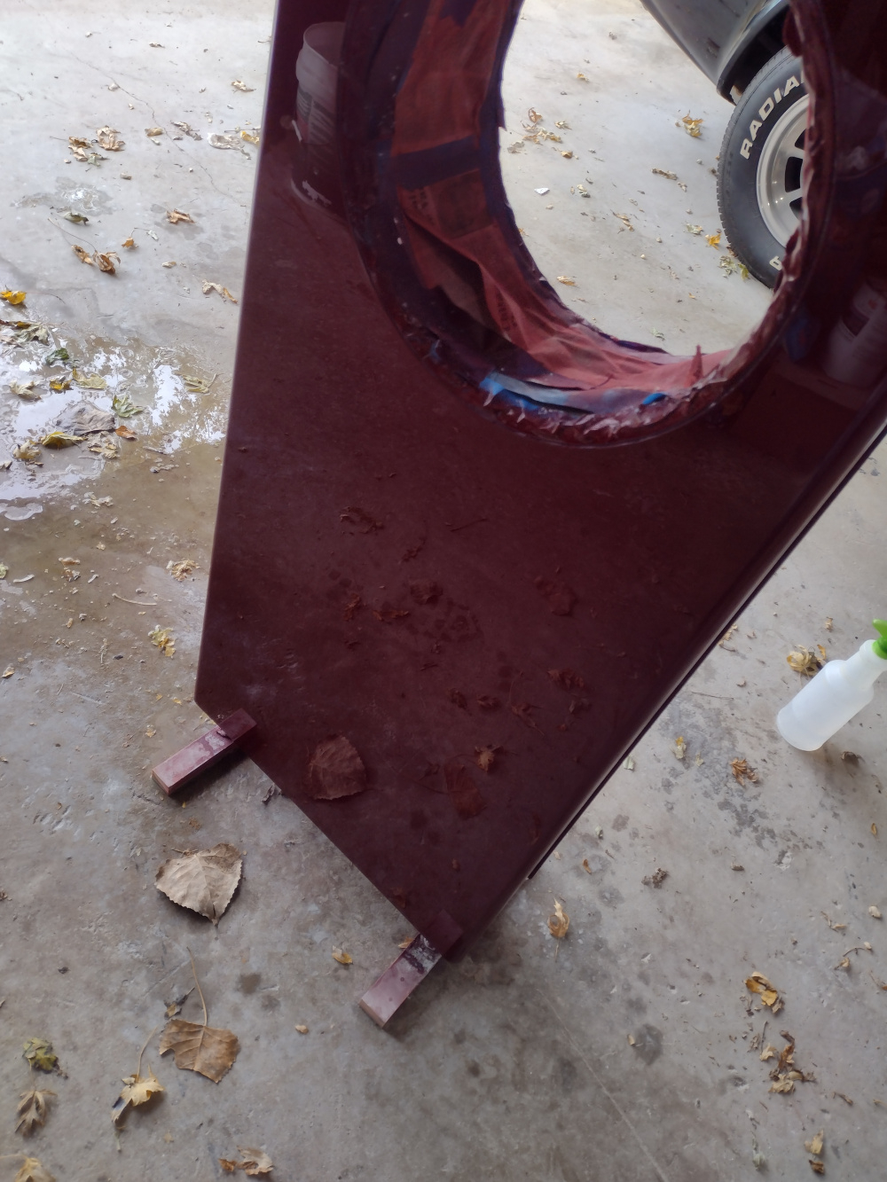
Most of you know that I took over this project from Dan. I've been slowly working on these and finally shot some color on them. I currently have one polished out.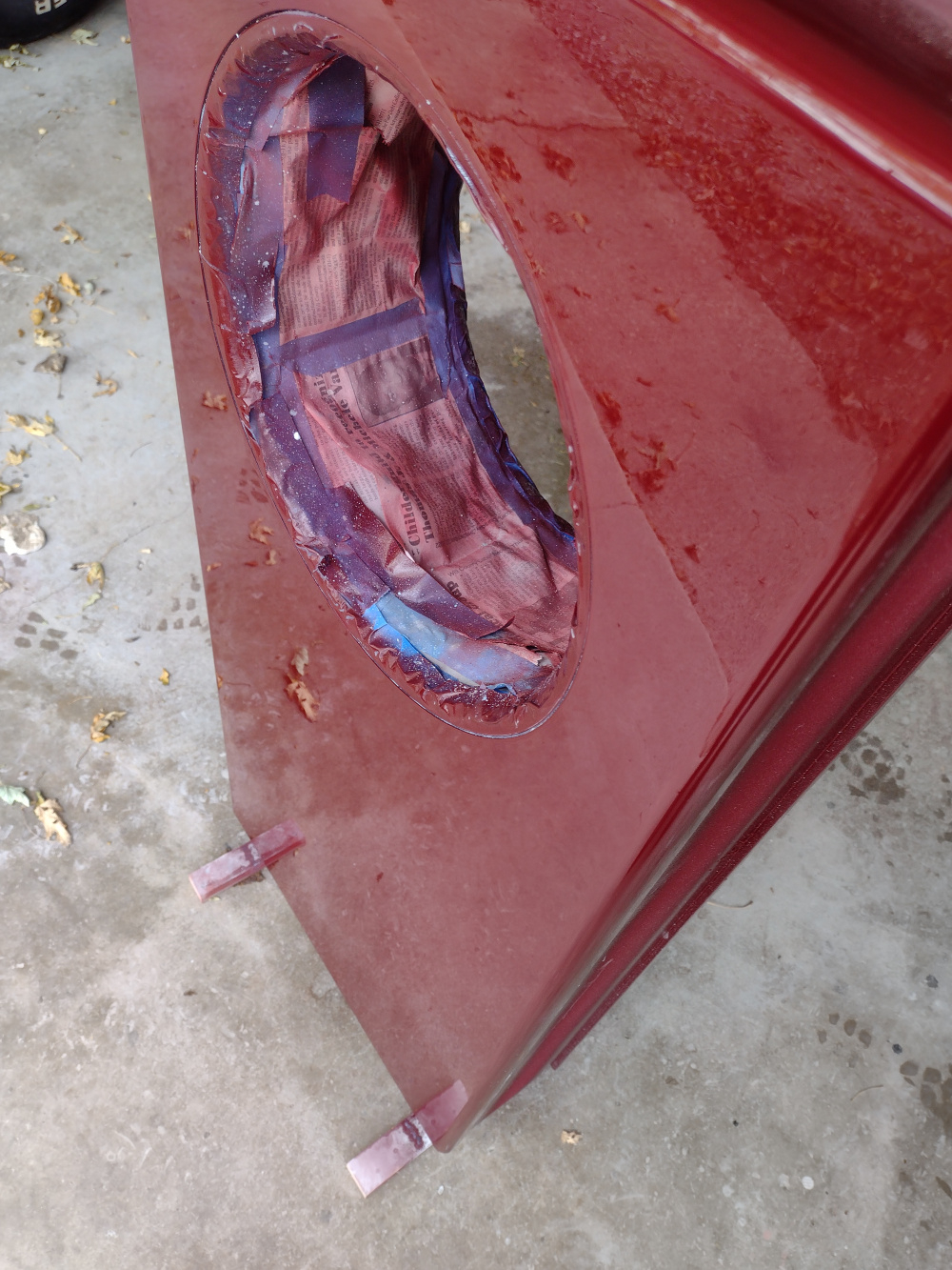
Nice!
InDIYana Event Website
I would have rather seen the Vette in the reflection, but I guess we'll settle for a glimpse of the wheel.😉
Ha, I wasn't thinking about that, I was trying to get the stupid camera to show the color more accurately. They're far too red in the first two photos. Photography is not my Forte.")
Yeah, good luck with that. Hard to capture colors that actually look like what it is in person.