I played around with the files a bit and have something that I think will work fairly well, though it's still a bit lumpy. No low impedance concern though. Bill, if you want to see what I've put together just say the word, otherwise have fun designing a crossover from here.
@dcibel said:
I played around with the files a bit and have something that I think will work fairly well, though it's still a bit lumpy. No low impedance concern though. Bill, if you want to see what I've put together just say the word, otherwise have fun designing a crossover from here.
Thanks, dcibel! Yes, I'd like to see what you came up with. But wait a couple weeks before posting it. This will give me time to work on my design a little bit more to see if I can solve the low impedance problem on my own.
PS: And thanks for the tips on the Conversion Tool. I have been reading the manuals. My problem is that I usually have to read the manuals three or four times before everything starts to sink in.
Definitely seems worth it so far. Once I had the loudspeaker clamped securely onto my DIY turntable setup, it only took me about 30 minutes to take all 39 spinorama measurements. It would have taken me much longer than this to take the 5 measurements per axis angle that I normally do with OmniMic. And then I have to calculate and enter offsets for each measurement set. Because of this, I would generally cut corners and simply measure on-axis plus two or three polar angles. I would load the data into XSim, but could only see the effects of one polar angle at a time when developing the xover. Flipping XSim driver icon sets back and forth to check polar angles was a real pain.
The nice thing about VituixCAD is that you get instant visual feedback with respect to the on-axis, off-axis, listening window, power, impedance, etc., as you tweak the xover parts. And you can easily run part values up and down with the mouse wheel. XSim can do some of the same things, but you only get instant feedback for one polar angle at a time. This makes a huge difference in my ability to understand what is really going on as I tweak and swap around xover parts.
@4thtry said:
Definitely seems worth it so far. Once I had the loudspeaker clamped securely onto my DIY turntable setup, it only took me about 30 minutes to take all 39 spinorama measurements.
The process can get even more streamlined if you move from SE to ARTA to REW, both of which have automated features for measuring the spatial data with automatic file naming.
In ARTA, its under the record menu -> spatial impulse response group record.
It's great to be able to measure as many drivers and angles as you want without having to think too much about it, avoid multiple measurements to determine offsets, HBT, min phase, etc. As well, single mic location measurements become increasingly inaccurate the bigger the speaker is. Okay for bookshelves, but with big towers the response at 1m mic axis can be quite a bit different than at 2m+ listening distance, even for your speaker I'm sure you will see a fairly different on-axis response if you change the listening distance in the options to 1m.
I noticed that ARTA can also be set up to work with motorized Outline turntables. If I had one of those, I could just sit back in my easy chair, press enter, and watch the computer churn out all the measurements for me.
I made several revisions to my initial model in an attempt to address some of the problem areas. Here is the revised 6 pack screen. Note that I increased the midrange high pass from 2nd to 3rd order because the midrange to woofer xover is a little bit lower than I would like (450 to 500Hz or so). This driver should probably be crossed higher, but I usually play my speakers at fairly low levels, so I should be OK.
Per Wolf's comments, I increased the impedance at 2kHz from 2.5 to about 3 ohms. Still fairly low, but that is the best I could do. I juggled the values around a bit for L5, R3, and R4 to accomplish this. As a side benefit, this change also softened the horizontal polar bunching and power response bump at 2kHz. You will notice that the impedance curve is showing a little glitch at about 120Hz. This is probably an internal cabinet resonance of some sort that I need to address with bracing or damping material.
Here is my Power & DI screen, showing how my In Room Response curve (orange) lines up with my 0.8dB/octave sloped target curve (pink). Note that I have the 100Hz end of the pink target curve lined up about 2dB above the In Room Response curve. This is to compensate for my 17" woofer to floor distance. This proximity effect will boost the low frequencies below about 250Hz by roughly 2dB or so, thus I need to apply 4dB of BSC instead of the full 6dB.
Here is my listening window and on-axis curve showing the 0.2dB/octave target curve. Again, the target is lined up about 2dB high on the 100Hz end to compensate for the 17" woofer to floor distance.
Lets see, 1/4 wavelength of 110Hz is 768mm, roughly the internal height of your cabinet I'd say...add more stuff. I'd suspect the amplitude dip at the same freq will come back a bit when you do.
Overall response is fairly good, but you've got a lot of parts in there as well. So do I but in a different arrangement, and the response I came up with is very similar. The impedance is on the low side but still okay for a proper 4 ohm capable amp. I'd be wary of driving the dome midrange that low however, the knee in the filter transfer function is down at 400Hz.
A few suggestions to try:
1. I like to add in random resistors here and there when fine tuning things, sometimes it makes all the difference. Try placing about 1.5 ohm in series with the woofer capacitor and re-adjusting those parts for example.
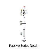
2. Try a series notch filter to address the upper midrange lump.
You can then try dropping a filter order and re-optimizing to see how it compares having a few less parts.
Remember as well that you can save 8 crossover variants in a given project, so you can make a lot of changes and then quickly swap back and forth between variants to compare the differences.
I'll note that the optimizer doesn't often deal well with notch filters so you may want to adjust them manually and leave those parts out of the optimizer routine.
Thanks for the excellent suggestions. I'll try these out and post another revision later today. After that, you can post your model as well. I am very interested to see what you came up with.
Here is yet another version with some of your suggestions. VituixCAD's crossover variant button is really cool, allowing you to quickly click through up to eight crossover versions. This makes it very easy to see if you are making improvements or making mistakes as you go along. As you can see, I was up to variant 7 on these changes:
1) Tweeter polarity reversed
2) Changed from 4th to 2nd order electrical filters on tweeter and mid
3) 1 ohm series resistor added to woofer capacitor leg
4) Series notch filter added to mid to suppress upper midrange glitch/hump
5) Minimum "Z" at 2kHz is now up to 3.4 ohms
6) Note: The mid to woofer xover is still a bit lower than I would like (500Hz). I tried to raise this higher, but this caused the "In Room Response" curve to suck out in the 400Hz to 1kHz region.
That looks very good, overall response is not that different from what I came up with, but still has the midrange playing quite low, in fact might be a bit worse then previously since the crossover slope is more shallow now.
I know that 3" dome midrange drivers generally don't perform well at low frequency, so the most complicated part of this design I found is the transition from a 10" woofer to a 3" dome midrange. With the goal of perfect in-room response in mind, I sacrifice a bit to keep the midrange driver in its happy region.
Here's the two options I came up with. Both options should be obtainable part values. All inductors air core, woofer inductor is 16AWG, all other inductors are 18AWG.
First allows the midrange breakup lump to shine through , so the worst part of this design is a dip at 2500Hz followed by a peak at 3500Hz, but we are only talking a couple dB here so it may sound just fine, I don't have distortion information for the driver to make a more educated decision.
Second option is simply taking a step further and addressing the midrange breakup with a notch filter, and adjusting many part values to suit.
Cool. I see you easily solved both the low impedance and low xover point problems that I was having. Thanks much for all your help. I feel like I have just finished attending a college level masterclass on advanced crossover design techniques.
I just finished one crossover board and listened to a single speaker for a couple hours. Really sounds good (or course, I'm biased). I used dcibel's basic topology and tweaked Vcad's woofer frd's to reduce BSC from the full 6dB to about 4dB (based on a revised Vcad diffraction model that properly takes into account the floor boundary reinforcement effect). I also tweaked all xover values to achieve the best NBD fixed and moving band preference ratings (see screenshots). Preliminary FR and impedance measurements show a fairly good match to my model.
Crossover:
Final 6 pack model:
NDB fixed and moving band preference rating screens:
If you're taking measurements to verify the model, just remember to change the listening distance in VituixCAD to mic measurement distance for direct comparison.
@jhollander said:
I'd be interested to see how the as measured compares to the model
That's on my agenda. Thanks for the tip, I'll be sure to change the listening distance to match the mic distance when comparing. I'd imagine that such a mis-match could really mess up the comparison, as the high frequencies probably tilt up quite a bit at close distances.
@4thtry said:
I'd imagine that such a mis-match could really mess up the comparison, as the high frequencies probably tilt up quite a bit at close distances.
Yes of course, and you will easily see how screwed up the crossover design could have been had you designed for flat response using only 1m single axis measurement with mic locked at tweeter axis, Xsim style. Even assuming the power response is still nice and flat, a fairly bloated sound would result simply from differing speaker distance to mic that tilts the entire response in favour of the closest driver, the tweeter.
Makes perfect sense. My preliminary on axis FR measurement at 1 meter using the calibrated dual channel mic and Soundeasy shows exactly what you are suggesting. The response slowly tilts up on axis when measured at 1 meter. Once I get the crossover mounted inside the cabinet, I'll do the full spinorama and post the results.
Today it got up to 55F with fairly low humidity (partly cloudy), so I set up my HVLP and shot 4 coats of lacquer. Borderline temperature-wise, but the flow was very good and the lacquer layed out well, creamy texture, good coverage, and no runs (just like I like it). I was going to keep shooting, maybe do 5 or 6 coats, but the temperature dipped down to 52 degrees so I decided to quit while I was ahead. I didn't want to risk losing the "flow" and messing up the nice finish that was starting to build up so far. Tomorrow is supposed to be in the 60's with low humidity, so my plan is to shoot another 4 or 5 coats tomorrow afternoon, as soon as the humidity goes down a little bit (it is usually too humid in the mornings).
@PWRRYD said:
They look great Bill! Will these be at InDIYana next month?
Thanks, Craig. Yup, that is the plan. I did a test fit the other day, and they will both slide easily into the back seat of my small Versa hatchback, even without flipping the seats back! All I have to do now is get the final lacquer coats sprayed tomorrow and then install the drivers (the crossovers are already done and glued to the bottoms behind the woofer holes.
@ugly_woofer said:
Cool! Are you going to cut and buff the lacquer?
If you mean like the pros do, creating a highly polished, high gloss lacquer finish, I don't think so. I did not use wood filler on the Mahogany, so it has quite a bit of grain texture, even after 4 coats of high gloss clear lacquer. At the end of tomorrow, I will have about 8 to 10 coats of high gloss clear lacquer build up on the Mahogany, but it will still have a slight wood grain texture. If I tried to buff this out to a smooth finish, I would probably go through the lacquer and hit the wood before it flattened out.
So my plan is to simply quit after about 8 to 10 coats of lacquer. This leaves a nice finish with a small amount of grain texture. This makes it look more like real wood, whereas a buffed out surface with wood filler tends to have more of a plastic type look and feel. I want to be able to feel the grain when I run my hand across the surface. If that makes sense.
About 6 months from now, I will plan to wax and polish the surface a little. But I do not want to do that now because the lacquer needs time to harden and gas off completely.
Thanks, guys. Much appreciated. I forgot to mention that I am using the cheapo Watco brushing lacquer from Menards, not the higher priced pre-cat type lacquer that they sell at specialty paint stores. To get the lacquer to spray properly throught my 1.2mm tip at 30psi, I am thinning the lacquer at a 3:2 ratio: 3 parts brushing lacquer to 2 parts lacquer thinner (approx at 67% to 33% mix). This ratio thins the lacquer out so that it can be sprayed. At the current temperature and humidity, this ratio keeps the "edge" wet as I spray back and forth in a short horizontal overlapping pattern.
Yeah, I actually like a nice matte/satin finish where the wood still has some natural grain and pores showing. Otherwise it just looks like my parents' formica table tops from the 70's 🤪
Comments
I played around with the files a bit and have something that I think will work fairly well, though it's still a bit lumpy. No low impedance concern though. Bill, if you want to see what I've put together just say the word, otherwise have fun designing a crossover from here.
Thanks, dcibel! Yes, I'd like to see what you came up with. But wait a couple weeks before posting it. This will give me time to work on my design a little bit more to see if I can solve the low impedance problem on my own.")
PS: And thanks for the tips on the Conversion Tool. I have been reading the manuals. My problem is that I usually have to read the manuals three or four times before everything starts to sink in.
That should keep my amplifier nice and warm. Will see if I can fix this on my own somehow without messing up the other curves too badly.
It you have specific questions just let me know.
Now that you’ve gone though The 2 channel process, was it worth the switch from the Omnimic?
Definitely seems worth it so far. Once I had the loudspeaker clamped securely onto my DIY turntable setup, it only took me about 30 minutes to take all 39 spinorama measurements. It would have taken me much longer than this to take the 5 measurements per axis angle that I normally do with OmniMic. And then I have to calculate and enter offsets for each measurement set. Because of this, I would generally cut corners and simply measure on-axis plus two or three polar angles. I would load the data into XSim, but could only see the effects of one polar angle at a time when developing the xover. Flipping XSim driver icon sets back and forth to check polar angles was a real pain.
The nice thing about VituixCAD is that you get instant visual feedback with respect to the on-axis, off-axis, listening window, power, impedance, etc., as you tweak the xover parts. And you can easily run part values up and down with the mouse wheel. XSim can do some of the same things, but you only get instant feedback for one polar angle at a time. This makes a huge difference in my ability to understand what is really going on as I tweak and swap around xover parts.
The process can get even more streamlined if you move from SE to ARTA to REW, both of which have automated features for measuring the spatial data with automatic file naming.
In ARTA, its under the record menu -> spatial impulse response group record.
It's great to be able to measure as many drivers and angles as you want without having to think too much about it, avoid multiple measurements to determine offsets, HBT, min phase, etc. As well, single mic location measurements become increasingly inaccurate the bigger the speaker is. Okay for bookshelves, but with big towers the response at 1m mic axis can be quite a bit different than at 2m+ listening distance, even for your speaker I'm sure you will see a fairly different on-axis response if you change the listening distance in the options to 1m.
I noticed that ARTA can also be set up to work with motorized Outline turntables. If I had one of those, I could just sit back in my easy chair, press enter, and watch the computer churn out all the measurements for me.")
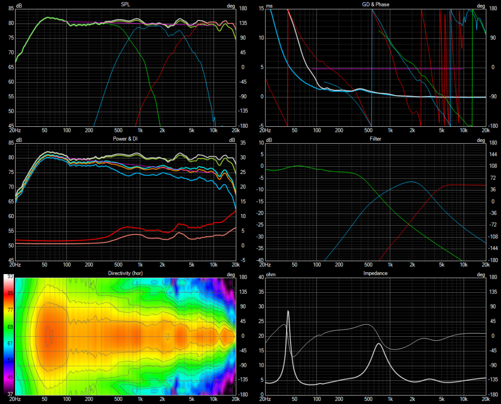
I made several revisions to my initial model in an attempt to address some of the problem areas. Here is the revised 6 pack screen. Note that I increased the midrange high pass from 2nd to 3rd order because the midrange to woofer xover is a little bit lower than I would like (450 to 500Hz or so). This driver should probably be crossed higher, but I usually play my speakers at fairly low levels, so I should be OK.
Per Wolf's comments, I increased the impedance at 2kHz from 2.5 to about 3 ohms. Still fairly low, but that is the best I could do. I juggled the values around a bit for L5, R3, and R4 to accomplish this. As a side benefit, this change also softened the horizontal polar bunching and power response bump at 2kHz. You will notice that the impedance curve is showing a little glitch at about 120Hz. This is probably an internal cabinet resonance of some sort that I need to address with bracing or damping material.
Here is my Power & DI screen, showing how my In Room Response curve (orange) lines up with my 0.8dB/octave sloped target curve (pink). Note that I have the 100Hz end of the pink target curve lined up about 2dB above the In Room Response curve. This is to compensate for my 17" woofer to floor distance. This proximity effect will boost the low frequencies below about 250Hz by roughly 2dB or so, thus I need to apply 4dB of BSC instead of the full 6dB.
Here is my listening window and on-axis curve showing the 0.2dB/octave target curve. Again, the target is lined up about 2dB high on the 100Hz end to compensate for the 17" woofer to floor distance.
Lets see, 1/4 wavelength of 110Hz is 768mm, roughly the internal height of your cabinet I'd say...add more stuff. I'd suspect the amplitude dip at the same freq will come back a bit when you do.
Overall response is fairly good, but you've got a lot of parts in there as well. So do I but in a different arrangement, and the response I came up with is very similar. The impedance is on the low side but still okay for a proper 4 ohm capable amp. I'd be wary of driving the dome midrange that low however, the knee in the filter transfer function is down at 400Hz.
A few suggestions to try:
1. I like to add in random resistors here and there when fine tuning things, sometimes it makes all the difference. Try placing about 1.5 ohm in series with the woofer capacitor and re-adjusting those parts for example.
2. Try a series notch filter to address the upper midrange lump.
I'll note that the optimizer doesn't often deal well with notch filters so you may want to adjust them manually and leave those parts out of the optimizer routine.
Thanks for the excellent suggestions. I'll try these out and post another revision later today. After that, you can post your model as well. I am very interested to see what you came up with.
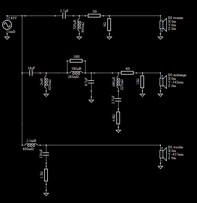
Here is yet another version with some of your suggestions. VituixCAD's crossover variant button is really cool, allowing you to quickly click through up to eight crossover versions. This makes it very easy to see if you are making improvements or making mistakes as you go along. As you can see, I was up to variant 7 on these changes:
1) Tweeter polarity reversed
2) Changed from 4th to 2nd order electrical filters on tweeter and mid
3) 1 ohm series resistor added to woofer capacitor leg
4) Series notch filter added to mid to suppress upper midrange glitch/hump
5) Minimum "Z" at 2kHz is now up to 3.4 ohms
6) Note: The mid to woofer xover is still a bit lower than I would like (500Hz). I tried to raise this higher, but this caused the "In Room Response" curve to suck out in the 400Hz to 1kHz region.
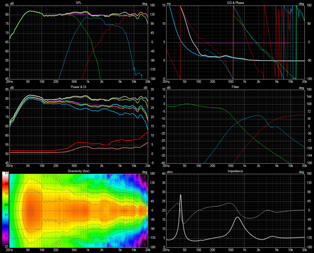
That looks very good, overall response is not that different from what I came up with, but still has the midrange playing quite low, in fact might be a bit worse then previously since the crossover slope is more shallow now.
I know that 3" dome midrange drivers generally don't perform well at low frequency, so the most complicated part of this design I found is the transition from a 10" woofer to a 3" dome midrange. With the goal of perfect in-room response in mind, I sacrifice a bit to keep the midrange driver in its happy region.
Here's the two options I came up with. Both options should be obtainable part values. All inductors air core, woofer inductor is 16AWG, all other inductors are 18AWG.
First allows the midrange breakup lump to shine through , so the worst part of this design is a dip at 2500Hz followed by a peak at 3500Hz, but we are only talking a couple dB here so it may sound just fine, I don't have distortion information for the driver to make a more educated decision.

Second option is simply taking a step further and addressing the midrange breakup with a notch filter, and adjusting many part values to suit.
Cool. I see you easily solved both the low impedance and low xover point problems that I was having. Thanks much for all your help. I feel like I have just finished attending a college level masterclass on advanced crossover design techniques.")
I wouldn't say easily, it is a fairly tricky speaker.")
I just finished one crossover board and listened to a single speaker for a couple hours. Really sounds good (or course, I'm biased). I used dcibel's basic topology and tweaked Vcad's woofer frd's to reduce BSC from the full 6dB to about 4dB (based on a revised Vcad diffraction model that properly takes into account the floor boundary reinforcement effect). I also tweaked all xover values to achieve the best NBD fixed and moving band preference ratings (see screenshots). Preliminary FR and impedance measurements show a fairly good match to my model.
Crossover:
Final 6 pack model:
NDB fixed and moving band preference rating screens:
I'd be interested to see how the as measured compares to the model
Looks good @4thtry !
If you're taking measurements to verify the model, just remember to change the listening distance in VituixCAD to mic measurement distance for direct comparison.
That's on my agenda. Thanks for the tip, I'll be sure to change the listening distance to match the mic distance when comparing. I'd imagine that such a mis-match could really mess up the comparison, as the high frequencies probably tilt up quite a bit at close distances.
Yes of course, and you will easily see how screwed up the crossover design could have been had you designed for flat response using only 1m single axis measurement with mic locked at tweeter axis, Xsim style. Even assuming the power response is still nice and flat, a fairly bloated sound would result simply from differing speaker distance to mic that tilts the entire response in favour of the closest driver, the tweeter.
Makes perfect sense. My preliminary on axis FR measurement at 1 meter using the calibrated dual channel mic and Soundeasy shows exactly what you are suggesting. The response slowly tilts up on axis when measured at 1 meter. Once I get the crossover mounted inside the cabinet, I'll do the full spinorama and post the results.
Today it got up to 55F with fairly low humidity (partly cloudy), so I set up my HVLP and shot 4 coats of lacquer. Borderline temperature-wise, but the flow was very good and the lacquer layed out well, creamy texture, good coverage, and no runs (just like I like it). I was going to keep shooting, maybe do 5 or 6 coats, but the temperature dipped down to 52 degrees so I decided to quit while I was ahead. I didn't want to risk losing the "flow" and messing up the nice finish that was starting to build up so far. Tomorrow is supposed to be in the 60's with low humidity, so my plan is to shoot another 4 or 5 coats tomorrow afternoon, as soon as the humidity goes down a little bit (it is usually too humid in the mornings).
They look great Bill! Will these be at InDIYana next month?
Thanks, Craig. Yup, that is the plan. I did a test fit the other day, and they will both slide easily into the back seat of my small Versa hatchback, even without flipping the seats back! All I have to do now is get the final lacquer coats sprayed tomorrow and then install the drivers (the crossovers are already done and glued to the bottoms behind the woofer holes.
Cool! Are you going to cut and buff the lacquer?
lots of practice -looks great
a skillset that is not in my toolbag
If you mean like the pros do, creating a highly polished, high gloss lacquer finish, I don't think so. I did not use wood filler on the Mahogany, so it has quite a bit of grain texture, even after 4 coats of high gloss clear lacquer. At the end of tomorrow, I will have about 8 to 10 coats of high gloss clear lacquer build up on the Mahogany, but it will still have a slight wood grain texture. If I tried to buff this out to a smooth finish, I would probably go through the lacquer and hit the wood before it flattened out.
So my plan is to simply quit after about 8 to 10 coats of lacquer. This leaves a nice finish with a small amount of grain texture. This makes it look more like real wood, whereas a buffed out surface with wood filler tends to have more of a plastic type look and feel. I want to be able to feel the grain when I run my hand across the surface. If that makes sense.
About 6 months from now, I will plan to wax and polish the surface a little. But I do not want to do that now because the lacquer needs time to harden and gas off completely.
Definitely looking forward to checking those out, fantastic job!🤘🏼
Thanks, guys. Much appreciated. I forgot to mention that I am using the cheapo Watco brushing lacquer from Menards, not the higher priced pre-cat type lacquer that they sell at specialty paint stores. To get the lacquer to spray properly throught my 1.2mm tip at 30psi, I am thinning the lacquer at a 3:2 ratio: 3 parts brushing lacquer to 2 parts lacquer thinner (approx at 67% to 33% mix). This ratio thins the lacquer out so that it can be sprayed. At the current temperature and humidity, this ratio keeps the "edge" wet as I spray back and forth in a short horizontal overlapping pattern.
Whatever you are doing seems to be working just fine. They look great!
Yeah, I actually like a nice matte/satin finish where the wood still has some natural grain and pores showing. Otherwise it just looks like my parents' formica table tops from the 70's 🤪