@4thtry said:
I did a comparison of a 400Hz splicing model verses a 650Hz splicing model. This produces an approx 2dB SPL change at 100Hz in the model. So, it looks like splicing at the appropriate frequency is critical when setting up your initial diffraction model.
The windowing function has a bit to do with it as well. Depending on the window function, you can end up filling in the low end response with some overshoot or undershoot. Kimmo recommends the cosine function for minimal overshoot, and I agree, with tukey 0.75 as a close second.
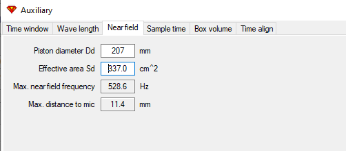
Keep in mind the nearfield response limitations as well based on driver size. For a 10" woofer..
Given these limitations, splicing in the 300-400Hz range in your first screenshot is "more correct". But as we've discussed, given a nearfield response with full diffraction model applied, effects of near floor placement are not included in the result so fine tuning the amount of baffle step gets a bit more complex. With your speaker elevated on a stand I would not expect there to be a great influence, but of course it's your speaker and room so let your ears be your guide
I agree. Fine tuning the baffle step is complex. This is the area where I keep making mistakes on builds because I do not seem to have the ability to accurately predict how much BSC is actually going to be needed before the crossover is completely assembled. The first order of business before you start building the crossover is to establish the woofers basic SPL at the 100-300Hz level. Then you bring the mid and tweeter SPL's down to match this basic level.
However, establishing the SPL at the 100-300Hz level tends to be somewhat of an art form. The accuracy (slope) of the FF woofer FRD is questionable below 500Hz due to the limited number of data points. And the accuracy of the NF woofer FRD is questionable above 500Hz due to the size of the woofer cone. Yet both curves need to have an overlapping area, where both are accurate, to perform an accurate splice!
To get around this problem, could I calibrate my testing room similar to the way anechoic chambers are calibrated at low frequencies? Build a small test box with a 6.5" woofer in it and then measure it at 1 meter outdoors on a 15 foot high stand in my back yard. Then bring this 6.5" woofer test box indoors, place it in the same position where a new speaker under development is being tested, measure it, and then use this data to calibrate my FF woofer and midrange measurements. Skip the entire NF/FF/Diff splicing process. Would this work?
@4thtry said:
I agree. Fine tuning the baffle step is complex. This is the area where I keep making mistakes on builds because I do not seem to have the ability to accurately predict how much BSC is actually going to be needed before the crossover is completely assembled. The first order of business before you start building the crossover is to establish the woofers basic SPL at the 100-300Hz level. Then you bring the mid and tweeter SPL's down to match this basic level.
However, establishing the SPL at the 100-300Hz level tends to be somewhat of an art form. The accuracy (slope) of the FF woofer FRD is questionable below 500Hz due to the limited number of data points. And the accuracy of the NF woofer FRD is questionable above 500Hz due to the size of the woofer cone. Yet both curves need to have an overlapping area, where both are accurate, to perform an accurate splice!
Yes, the bigger the driver the harder it is to get a good full-frequency response indoors. I think what you have shows above is just fine however, the overlap of responses is good right down to nearly 200Hz.
To get around this problem, could I calibrate my testing room similar to the way anechoic chambers are calibrated at low frequencies? Build a small test box with a 6.5" woofer in it and then measure it at 1 meter outdoors on a 15 foot high stand in my back yard. Then bring this 6.5" woofer test box indoors, place it in the same position where a new speaker under development is being tested, measure it, and then use this data to calibrate my FF woofer and midrange measurements. Skip the entire NF/FF/Diff splicing process. Would this work?
Well...that certainly is an idea, but it isn't going to fix any problems you currently have. If you manage to work out a "calibration", it will simply be replacing the near field measurement, and to be honest moving the mic to the near field is probably easier than swapping out the entire speaker for a "calibration woofer box". Anechoic chambers use this type of calibration with a stationary mic, so the speaker is elevated in the room to the mic. I don't know about you but I like the convenience of being able to put the mic where I want and then nearfield.
I don't want to presume, but one suggestion I would make though is to make sure the cabinet is fully stuffed when measuring the woofer. An impedance bump and response dip at 110Hz is affecting that ever so critical frequency range which I can only assume is a cabinet reflection.
Another consideration if the problem is more low end "boom" than bloated midbass, is that the woofer filter you have is providing a bit of accentuation to the 50Hz range. This is a result of a high Q woofer impedance, again can be tamed with cabinet stuffing.
Isn't that always the last thing we 'measure'? We pound the squiggly lines into submission until we achieve something as flat as Kansas, then a few weeks later we actually stop to listen to 'em. I'm just as guilty!
@4thtry said:
I agree. Fine tuning the baffle step is complex. This is the area where I keep making mistakes on builds because I do not seem to have the ability to accurately predict how much BSC is actually going to be needed before the crossover is completely assembled. The first order of business before you start building the crossover is to establish the woofers basic SPL at the 100-300Hz level. Then you bring the mid and tweeter SPL's down to match this basic level.
However, establishing the SPL at the 100-300Hz level tends to be somewhat of an art form. The accuracy (slope) of the FF woofer FRD is questionable below 500Hz due to the limited number of data points. And the accuracy of the NF woofer FRD is questionable above 500Hz due to the size of the woofer cone. Yet both curves need to have an overlapping area, where both are accurate, to perform an accurate splice!
Yes, the bigger the driver the harder it is to get a good full-frequency response indoors. I think what you have shows above is just fine however, the overlap of responses is good right down to nearly 200Hz.
To get around this problem, could I calibrate my testing room similar to the way anechoic chambers are calibrated at low frequencies? Build a small test box with a 6.5" woofer in it and then measure it at 1 meter outdoors on a 15 foot high stand in my back yard. Then bring this 6.5" woofer test box indoors, place it in the same position where a new speaker under development is being tested, measure it, and then use this data to calibrate my FF woofer and midrange measurements. Skip the entire NF/FF/Diff splicing process. Would this work?
Well...that certainly is an idea, but it isn't going to fix any problems you currently have. If you manage to work out a "calibration", it will simply be replacing the near field measurement, and to be honest moving the mic to the near field is probably easier than swapping out the entire speaker for a "calibration woofer box". Anechoic chambers use this type of calibration with a stationary mic, so the speaker is elevated in the room to the mic. I don't know about you but I like the convenience of being able to put the mic where I want and then nearfield.
I don't want to presume, but one suggestion I would make though is to make sure the cabinet is fully stuffed when measuring the woofer. An impedance bump and response dip at 110Hz is affecting that ever so critical frequency range which I can only assume is a cabinet reflection.
Another consideration if the problem is more low end "boom" than bloated midbass, is that the woofer filter you have is providing a bit of accentuation to the 50Hz range. This is a result of a high Q woofer impedance, again can be tamed with cabinet stuffing.
The calibration would just serve as a sanity check, to double check the splicing process for potential errors. The sloping overlap looks good down to 200Hz, but that may be an illusion created by errors in either the NF measurement, the FF measurement, or the diffraction model applied.
I'm not sure what that 110Hz blip on the impedance curve is. It shows up on both the modelled and measured Z curves. For both measurements, the cabinet was stuffed in a similar manner. The upper half of the cabinet down to about the level of the midrange was stuffed with a batt of ultratouch denim insulation, at a rate of about 1lb/cu. ft. The lower half of the cabinet was lined on all sides with 1/2" fiberglass (Armstrong pebble 2x4 ceiling tile material with the white plastic pebble surface removed). Fb tuning is somewhere in the 24 to 26Hz range. Not sure about 50Hz booming. Is there any way that I can test to see if the woofer filter is causing a boom at 50Hz? My WinISD model does not include crossover parts.
@4thtry said:
The calibration would just serve as a sanity check
One "sanity check" could be to give your crossover design a listen for overall tonality before you commit to purchasing parts and assembling it. If you recall I had detailed a process in which you can use VituixCAD and APO EQ to simulate any filter transfer function in the digital domain. Most PC soundcards include 6 (5.1) or 8(7.1) channels to provide flexibility of setting up an average PC as a crossover simulator. HDMI output to an AVR could do the trick as well.
I'm not sure what that 110Hz blip on the impedance curve is. It shows up on both the modelled and measured Z curves.
It's in the modelled cabinet model? In WinISD with "transmission line for port simulation" enabled? It could very well be port resonance, and in fact does show up clearly in your port measurement.
@4thtry said:
Not sure about 50Hz booming. Is there any way that I can test to see if the woofer filter is causing a boom at 50Hz? My WinISD model does not include crossover parts.
This is what I'm referring to. This bump primarily exists because the impedance is high in this frequency range. Adding fill to the cabinet can dampen the impedance, and the filter interaction will follow suit. I wouldn't worry about it unless you actually find it sounds boomy.
@tajanes said:
Sorry if I missed port tuning in this series, but do you have a frequency measurement at the port?
If, by chance it centers around 50Hz +/-, maybe try either extending to lower, and/or maybe just lightly fill to try to reduce its output?
As dcibel suggested, I added some fill to dampen the resonance and this worked!! It now sounds much better. Bass goes just as deep without the bloated boomyness.
Here is what I did: I added a folded 3x10x12" layer (total of 6 inches thick) of Ultratouch denim insulation on top of the crossover board, which sits at the bottom of the cabinet. The top of the cabinet is already filled with denim down to about the level of the midrange. So this leaves an open resonating chamber in the center of the cabinet that is only lined on all sides with 1/2" thick fiberglass. The port and back of the speaker cone are not blocked in any way.
There appears to be a small port peak at 110Hz, which may be related to the Z curve glitch.
@4thtry said:
The calibration would just serve as a sanity check
One "sanity check" could be to give your crossover design a listen for overall tonality before you commit to purchasing parts and assembling it. If you recall I had detailed a process in which you can use VituixCAD and APO EQ to simulate any filter transfer function in the digital domain. Most PC soundcards include 6 (5.1) or 8(7.1) channels to provide flexibility of setting up an average PC as a crossover simulator. HDMI output to an AVR could do the trick as well.
I have decided to take these speakers to the Speaker Design Competition in August (aka MWAF). But my hacked up DIY woofer flanges look pretty bad and are in need of cosmetic trim rings. So I picked up a 6 foot length of 1x4 Mahogany at Menards ($14.99 less 11%). This will be just enough material to do both woofers. I'm shifting the grain pattern abruptly to eliminate end grain on the top and bottom edges. I think this will look a little bit better because Mahogany end grain really soaks up the finish. Hopefully this will turn out well.
@ugly_woofer said:
How about making a hexagon or octagon and then cutting the ring.
Thanks for the suggestion. I thought about doing that, but decided to try this first because it is much easier to calculate and clamp up a simple rectangular shape. With a hexagon or octagon, I figured that it would have taken me much longer to lay out the dimensions and angles in photoshop. And I would still have had the problem of seeing shifts in the grain pattern as my eye moved around the circle. The shifts would be much smaller and blend together better, but the number of shifts increases. The rectangular box method will produce a 45 degree angle grain shift around 4 corners. A hexagon will produce a 30 degree angle grain shift around 6 corners. And a octagon will produce a 22.5 degree grain shift around 8 corners.
I'll give the rectangle a shot first. If it looks bad after finish, I'll head back to Menards and try an octagon.
Does grain filler work very well on Mahogany? I don't often use stains or dark wood so I can typically get by with just rubbing wood filler into the end grain and it definitely helps lighten up under a clear coat.
@DrewsBrews said:
Does grain filler work very well on Mahogany? I don't often use stains or dark wood so I can typically get by with just rubbing wood filler into the end grain and it definitely helps lighten up under a clear coat.
Sorry, I'm not the person to ask about grain filler. Others on this forum know much more about grain fillers than I do, so maybe someone else will chime in with an answer to your question. All of my experiences with grain fillers have been bad ones, so I shy away from using it. Plus, it is alot more work. I did not use grain filler on the Mahogany in this project because I wanted the texture of the wood to show through the final lacquer finish. So when I run my hand across the wood I can feel the texture.
Before the glue up, I applied masking tape along all the glue edges to keep the glue from bleeding into the wood:
This worked well. After removing the tape, the mohagany is very clean along the edges:
After removing all the masking tape, I rigidly clamped both mahogany rings into a fixture with spacers to keep the rings perfectly flat and prevent warpage as the glue sets. I will keep the rings in this clamped fixture for at least 3 days. At this point, the glue has set for only about 12 hours and is still wet inside the joint.
A little background: I remember a nice looking pair of speakers that used large curly maple woofer and mid/tweeter rings, contrasted against a much darker (mahogany?) baffle and cabinet. They were called the "Exponents" and were demo'd by George (moosespeaker) at InDIYana and MWAF 2014. This speaker inspired me to give this a try, only in reverse, using a dark mahogany woofer ring to contrast against a much lighter curly maple baffle board.
Routing a clearance rebate on the underside to match the woofer flange profile.
Routing the inner ring profile.
Driver mounting clearance holes and inner/outer roundovers done:
Woofer flange to ring mounting detail:
Here is how it looks without the ring:
Here is how they should look with the rings installed. I just tipped one speaker onto its back & placed one ring on the flange for the picture. They will be glued on later when the finishing is done. Right now, the rings have received just one coat of Craig's 1:1:1 BLO mix, which is still drying. I'll probably give the rings another coat or two of the BLO mix, then wait 2 weeks, then spray them with about 10 coats of high gloss clear lacquer. I still have plenty of time to get this done before the SDC. Will report back in a month or so with a few finished pics of both speakers.
Maybe I'm just confused. Are you trying to hide the ugly stamped steel baskets, because I can still see their outer rim? What's the light colored material between the woofer's surround and the trim ring?
The light colored material is the inside edge of the masonite ring. I plan to stain this edge with the BLO mix, which should make it blend away. The outer rim of the steel baskets will still be visible; I plan to sand this edge and re-paint it black. Probably not the best idea, but I think it will look OK. My initial plan was to make the mahogany ring bigger to cover the entire woofer basket, but I decided against this because this would have required thicker mahogany (1" or greater). I was trying to get by with a single 6 foot length of Menard's cheap 3/4" material. Due to the rebate, the outer edge is slightly less that 3/8" thick. This was not thick enough to handle an additional 1/4" + rebate to cover the rim and woofer gasket.
During a recent painting session, I dropped one of my re-foamed 12" woofers, magnet first, onto the cement garage floor. The impact broke the epoxy holding the back plate/pole piece and froze the VC.
So now I have to replace both woofers. After going through my inventory, I decided to use my pair of 10" RS270P-8 woofers. As luck would have it, the RS270 produces an almost perfect WinISD alignment for my box and port dimensions (F3/6/10 - 30/25/22). So, I modified my mahogany adapter rings by gluing a new 7/32" thick masonite adapter ring to the bottom side of the original ring and drilled 6 new mounting holes for the RS270P's.
The RS270P mounts to the inside of the mahogany ring with a gasket and the ring itself mounts to the cabinet with another gasket.
Here is the finished product:
That takes care of the mechanical mods. Now I have to run up a new set of measurements and modify the xovers to account for differences in sensitivity, impedance, FR, and phase.
Thanks, Tom. That was a real shame, losing those woofers. As you can see in the pic, the 2" voice coils were 35mm high, the mfg spec'd them as 12mm Xmax. Xmech was probably about 18mm. They were originally designed for use in a passive Audio Concepts subwoofer system back in the 1990's.
Been working on the xovers for a few days to replace the woofers with RS270P-8's. I ran up a new set of measurements for these woofers and have come up with the below revised schematic (6 changes highlighted in yellow). Everything else is the same. I'll attach the new 6 pack model and then some of the individual 25dB/decade graphs for clarity. It's hard to see the detail in the 6 pack model alone.
Revised xover:
Revised 6 pack model:
On-axis FR and Listening window (25dB/decade aspect ratio). Crossovers are now 750 and approx 4kHz. The upper xover is probably a little bit too high, as this is causing a very narrow vertical lobe in the presence region. Also, the woofer breakup at 2-3kHz is only about 15dB down. On the positive side, the on-axis FR is plus or minus 1dB from 50 to 20,000Hz!
Power & DI screen at 25dB/decade. Nice, smooth downward sloping power response and PIR curves. Smooth gentle upward slope on the bottom most ERDI curve.
Horizontal directivity looks very smooth all the way out to 90 degrees. The first graph is the line chart and the 2nd graph is the heat map version:
Now for the bad news: Here is the vertical directivity out to 45 degrees. The first graph is the line chart and the 2nd graph is the heat map version. Notice how narrow the vertical becomes in the presence region. This is due to the driver spacing (approx 5.5" ctr to ctr) and the high xover frequency (4kHz). I think I need to do something about this.
Finally, here is the Group Delay and Phase chart. Very good phase tracking between drivers. Group delay is very low, 0.5ms or less down to 300Hz, then bumps up to 1ms at 200Hz, 3ms at 100Hz, and 10ms at 50Hz. Looks OK to me for a standard bass reflex type design.
@Steve_Lee said:
Is the room causing any of these abrupt vertical dispersion dips @10 & 20* off-axis or just driver spacing on the MT section (as you suggest)?
Everything else looks incredibly good to me as a casual observer.
Thanks, Steve. No, these dips would not be the room. The modeled vertical curves are quasi-anechoic. Room reflections have been gated out. I think this is simply a function of driver spacing and the high xover frequency of 4kHz. One half wavelength at 4kHz is 1.69 inches. That is probably the difference to the tweeter and midrange driver cones from a distance of 2.5 meters at 10 degrees vertical.
I still have the old xover installed in the speaker, so I have been listening to this problem to see how bad (or good) it sounds. You can definitely hear the highs roll off when you stand up from a seated position. I did some "high flying" type vertical sweeps with OmniMic and discovered that the lobe tilts down by 5 degrees or so. So if I tilt the speakers back by 5 degrees, there is no difference in the sound or the measurement between the seated and standing positions. I really like the way it sounds, the tweeter and mid blend together very well. So I may just leave the xover the way it is and modify my stands to tilt the speaker back by 5 degrees.
Great looking speakers Bill and it looks like you've almost got the xo's nailed (sans the woofer break up which I'm sure you'll address).
Question: My RS270P-4 woofers have the typical "Dayton RS" extended pole pieces. Your RS270P-8 appear to have dust caps. Did I miss where you knocked out the extended pole pieces and glued on dust caps?
Comments
The windowing function has a bit to do with it as well. Depending on the window function, you can end up filling in the low end response with some overshoot or undershoot. Kimmo recommends the cosine function for minimal overshoot, and I agree, with tukey 0.75 as a close second.
Keep in mind the nearfield response limitations as well based on driver size. For a 10" woofer..
Given these limitations, splicing in the 300-400Hz range in your first screenshot is "more correct". But as we've discussed, given a nearfield response with full diffraction model applied, effects of near floor placement are not included in the result so fine tuning the amount of baffle step gets a bit more complex. With your speaker elevated on a stand I would not expect there to be a great influence, but of course it's your speaker and room so let your ears be your guide")
I agree. Fine tuning the baffle step is complex. This is the area where I keep making mistakes on builds because I do not seem to have the ability to accurately predict how much BSC is actually going to be needed before the crossover is completely assembled. The first order of business before you start building the crossover is to establish the woofers basic SPL at the 100-300Hz level. Then you bring the mid and tweeter SPL's down to match this basic level.
However, establishing the SPL at the 100-300Hz level tends to be somewhat of an art form. The accuracy (slope) of the FF woofer FRD is questionable below 500Hz due to the limited number of data points. And the accuracy of the NF woofer FRD is questionable above 500Hz due to the size of the woofer cone. Yet both curves need to have an overlapping area, where both are accurate, to perform an accurate splice!
To get around this problem, could I calibrate my testing room similar to the way anechoic chambers are calibrated at low frequencies? Build a small test box with a 6.5" woofer in it and then measure it at 1 meter outdoors on a 15 foot high stand in my back yard. Then bring this 6.5" woofer test box indoors, place it in the same position where a new speaker under development is being tested, measure it, and then use this data to calibrate my FF woofer and midrange measurements. Skip the entire NF/FF/Diff splicing process. Would this work?
Yes, the bigger the driver the harder it is to get a good full-frequency response indoors. I think what you have shows above is just fine however, the overlap of responses is good right down to nearly 200Hz.
Well...that certainly is an idea, but it isn't going to fix any problems you currently have. If you manage to work out a "calibration", it will simply be replacing the near field measurement, and to be honest moving the mic to the near field is probably easier than swapping out the entire speaker for a "calibration woofer box". Anechoic chambers use this type of calibration with a stationary mic, so the speaker is elevated in the room to the mic. I don't know about you but I like the convenience of being able to put the mic where I want and then nearfield.
I don't want to presume, but one suggestion I would make though is to make sure the cabinet is fully stuffed when measuring the woofer. An impedance bump and response dip at 110Hz is affecting that ever so critical frequency range which I can only assume is a cabinet reflection.
Another consideration if the problem is more low end "boom" than bloated midbass, is that the woofer filter you have is providing a bit of accentuation to the 50Hz range. This is a result of a high Q woofer impedance, again can be tamed with cabinet stuffing.
Isn't that always the last thing we 'measure'? We pound the squiggly lines into submission until we achieve something as flat as Kansas, then a few weeks later we actually stop to listen to 'em. I'm just as guilty!
And Bill, those are awesome!
The calibration would just serve as a sanity check, to double check the splicing process for potential errors. The sloping overlap looks good down to 200Hz, but that may be an illusion created by errors in either the NF measurement, the FF measurement, or the diffraction model applied.
I'm not sure what that 110Hz blip on the impedance curve is. It shows up on both the modelled and measured Z curves. For both measurements, the cabinet was stuffed in a similar manner. The upper half of the cabinet down to about the level of the midrange was stuffed with a batt of ultratouch denim insulation, at a rate of about 1lb/cu. ft. The lower half of the cabinet was lined on all sides with 1/2" fiberglass (Armstrong pebble 2x4 ceiling tile material with the white plastic pebble surface removed). Fb tuning is somewhere in the 24 to 26Hz range. Not sure about 50Hz booming. Is there any way that I can test to see if the woofer filter is causing a boom at 50Hz? My WinISD model does not include crossover parts.
Sorry if I missed port tuning in this series, but do you have a frequency measurement at the port?
If, by chance it centers around 50Hz +/-, maybe try either extending to lower, and/or maybe just lightly fill to try to reduce its output?
One "sanity check" could be to give your crossover design a listen for overall tonality before you commit to purchasing parts and assembling it. If you recall I had detailed a process in which you can use VituixCAD and APO EQ to simulate any filter transfer function in the digital domain. Most PC soundcards include 6 (5.1) or 8(7.1) channels to provide flexibility of setting up an average PC as a crossover simulator. HDMI output to an AVR could do the trick as well.
https://diy.midwestaudio.club/discussion/1832/simulating-crossover-filters-with-vituixcad-and-eq-apo
It's in the modelled cabinet model? In WinISD with "transmission line for port simulation" enabled? It could very well be port resonance, and in fact does show up clearly in your port measurement.
This is what I'm referring to. This bump primarily exists because the impedance is high in this frequency range. Adding fill to the cabinet can dampen the impedance, and the filter interaction will follow suit. I wouldn't worry about it unless you actually find it sounds boomy.
As dcibel suggested, I added some fill to dampen the resonance and this worked!! It now sounds much better. Bass goes just as deep without the bloated boomyness.
Here is what I did: I added a folded 3x10x12" layer (total of 6 inches thick) of Ultratouch denim insulation on top of the crossover board, which sits at the bottom of the cabinet. The top of the cabinet is already filled with denim down to about the level of the midrange. So this leaves an open resonating chamber in the center of the cabinet that is only lined on all sides with 1/2" thick fiberglass. The port and back of the speaker cone are not blocked in any way.
There appears to be a small port peak at 110Hz, which may be related to the Z curve glitch.
This is on my agenda. Thanks again for all your help!!
My pleasure.
The port resonance is quite clear in the measurement data you provided some pages back, even more so than what you show above.
I have decided to take these speakers to the Speaker Design Competition in August (aka MWAF). But my hacked up DIY woofer flanges look pretty bad and are in need of cosmetic trim rings. So I picked up a 6 foot length of 1x4 Mahogany at Menards ($14.99 less 11%). This will be just enough material to do both woofers. I'm shifting the grain pattern abruptly to eliminate end grain on the top and bottom edges. I think this will look a little bit better because Mahogany end grain really soaks up the finish. Hopefully this will turn out well.
How about making a hexagon or octagon and then cutting the ring.
Thanks for the suggestion. I thought about doing that, but decided to try this first because it is much easier to calculate and clamp up a simple rectangular shape. With a hexagon or octagon, I figured that it would have taken me much longer to lay out the dimensions and angles in photoshop. And I would still have had the problem of seeing shifts in the grain pattern as my eye moved around the circle. The shifts would be much smaller and blend together better, but the number of shifts increases. The rectangular box method will produce a 45 degree angle grain shift around 4 corners. A hexagon will produce a 30 degree angle grain shift around 6 corners. And a octagon will produce a 22.5 degree grain shift around 8 corners.
I'll give the rectangle a shot first. If it looks bad after finish, I'll head back to Menards and try an octagon.")
Does grain filler work very well on Mahogany? I don't often use stains or dark wood so I can typically get by with just rubbing wood filler into the end grain and it definitely helps lighten up under a clear coat.
Sorry, I'm not the person to ask about grain filler. Others on this forum know much more about grain fillers than I do, so maybe someone else will chime in with an answer to your question. All of my experiences with grain fillers have been bad ones, so I shy away from using it. Plus, it is alot more work. I did not use grain filler on the Mahogany in this project because I wanted the texture of the wood to show through the final lacquer finish. So when I run my hand across the wood I can feel the texture.
Before the glue up, I applied masking tape along all the glue edges to keep the glue from bleeding into the wood:
This worked well. After removing the tape, the mohagany is very clean along the edges:
After removing all the masking tape, I rigidly clamped both mahogany rings into a fixture with spacers to keep the rings perfectly flat and prevent warpage as the glue sets. I will keep the rings in this clamped fixture for at least 3 days. At this point, the glue has set for only about 12 hours and is still wet inside the joint.
A little background: I remember a nice looking pair of speakers that used large curly maple woofer and mid/tweeter rings, contrasted against a much darker (mahogany?) baffle and cabinet. They were called the "Exponents" and were demo'd by George (moosespeaker) at InDIYana and MWAF 2014. This speaker inspired me to give this a try, only in reverse, using a dark mahogany woofer ring to contrast against a much lighter curly maple baffle board.
He won his category too. Those sounded great!
InDIYana Event Website
Some Progress:
Routing outer ring diameter:
Routing a clearance rebate on the underside to match the woofer flange profile.
Routing the inner ring profile.
Driver mounting clearance holes and inner/outer roundovers done:
Woofer flange to ring mounting detail:
Here is how it looks without the ring:
Here is how they should look with the rings installed. I just tipped one speaker onto its back & placed one ring on the flange for the picture. They will be glued on later when the finishing is done. Right now, the rings have received just one coat of Craig's 1:1:1 BLO mix, which is still drying. I'll probably give the rings another coat or two of the BLO mix, then wait 2 weeks, then spray them with about 10 coats of high gloss clear lacquer. I still have plenty of time to get this done before the SDC. Will report back in a month or so with a few finished pics of both speakers.
Maybe I'm just confused. Are you trying to hide the ugly stamped steel baskets, because I can still see their outer rim? What's the light colored material between the woofer's surround and the trim ring?
The light colored material is the inside edge of the masonite ring. I plan to stain this edge with the BLO mix, which should make it blend away. The outer rim of the steel baskets will still be visible; I plan to sand this edge and re-paint it black. Probably not the best idea, but I think it will look OK. My initial plan was to make the mahogany ring bigger to cover the entire woofer basket, but I decided against this because this would have required thicker mahogany (1" or greater). I was trying to get by with a single 6 foot length of Menard's cheap 3/4" material. Due to the rebate, the outer edge is slightly less that 3/8" thick. This was not thick enough to handle an additional 1/4" + rebate to cover the rim and woofer gasket.
Off the cuff, I'd paint that inner masonite ring black along with the outer frame edge. Otherwise, it's a definite improvement!
During a recent painting session, I dropped one of my re-foamed 12" woofers, magnet first, onto the cement garage floor. The impact broke the epoxy holding the back plate/pole piece and froze the VC.
So now I have to replace both woofers. After going through my inventory, I decided to use my pair of 10" RS270P-8 woofers. As luck would have it, the RS270 produces an almost perfect WinISD alignment for my box and port dimensions (F3/6/10 - 30/25/22). So, I modified my mahogany adapter rings by gluing a new 7/32" thick masonite adapter ring to the bottom side of the original ring and drilled 6 new mounting holes for the RS270P's.
The RS270P mounts to the inside of the mahogany ring with a gasket and the ring itself mounts to the cabinet with another gasket.
Here is the finished product:
That takes care of the mechanical mods. Now I have to run up a new set of measurements and modify the xovers to account for differences in sensitivity, impedance, FR, and phase.
Just the sight of that broken woofer made me cringe. Glad you were able to salvage the project!
Thanks, Tom. That was a real shame, losing those woofers. As you can see in the pic, the 2" voice coils were 35mm high, the mfg spec'd them as 12mm Xmax. Xmech was probably about 18mm. They were originally designed for use in a passive Audio Concepts subwoofer system back in the 1990's.
Been working on the xovers for a few days to replace the woofers with RS270P-8's. I ran up a new set of measurements for these woofers and have come up with the below revised schematic (6 changes highlighted in yellow). Everything else is the same. I'll attach the new 6 pack model and then some of the individual 25dB/decade graphs for clarity. It's hard to see the detail in the 6 pack model alone.
Revised xover:
Revised 6 pack model:
On-axis FR and Listening window (25dB/decade aspect ratio). Crossovers are now 750 and approx 4kHz. The upper xover is probably a little bit too high, as this is causing a very narrow vertical lobe in the presence region. Also, the woofer breakup at 2-3kHz is only about 15dB down. On the positive side, the on-axis FR is plus or minus 1dB from 50 to 20,000Hz!
Power & DI screen at 25dB/decade. Nice, smooth downward sloping power response and PIR curves. Smooth gentle upward slope on the bottom most ERDI curve.
Horizontal directivity looks very smooth all the way out to 90 degrees. The first graph is the line chart and the 2nd graph is the heat map version:
Now for the bad news: Here is the vertical directivity out to 45 degrees. The first graph is the line chart and the 2nd graph is the heat map version. Notice how narrow the vertical becomes in the presence region. This is due to the driver spacing (approx 5.5" ctr to ctr) and the high xover frequency (4kHz). I think I need to do something about this.
Finally, here is the Group Delay and Phase chart. Very good phase tracking between drivers. Group delay is very low, 0.5ms or less down to 300Hz, then bumps up to 1ms at 200Hz, 3ms at 100Hz, and 10ms at 50Hz. Looks OK to me for a standard bass reflex type design.
Is the room causing any of these abrupt vertical dispersion dips @10 & 20* off-axis or just driver spacing on the MT section (as you suggest)?
Everything else looks incredibly good to me as a casual observer.
This is one where I definitely want to spend time listening to hear what's going on at 4K up
Thanks, Steve. No, these dips would not be the room. The modeled vertical curves are quasi-anechoic. Room reflections have been gated out. I think this is simply a function of driver spacing and the high xover frequency of 4kHz. One half wavelength at 4kHz is 1.69 inches. That is probably the difference to the tweeter and midrange driver cones from a distance of 2.5 meters at 10 degrees vertical.
I still have the old xover installed in the speaker, so I have been listening to this problem to see how bad (or good) it sounds. You can definitely hear the highs roll off when you stand up from a seated position. I did some "high flying" type vertical sweeps with OmniMic and discovered that the lobe tilts down by 5 degrees or so. So if I tilt the speakers back by 5 degrees, there is no difference in the sound or the measurement between the seated and standing positions. I really like the way it sounds, the tweeter and mid blend together very well. So I may just leave the xover the way it is and modify my stands to tilt the speaker back by 5 degrees.
Great looking speakers Bill and it looks like you've almost got the xo's nailed (sans the woofer break up which I'm sure you'll address).
Question: My RS270P-4 woofers have the typical "Dayton RS" extended pole pieces. Your RS270P-8 appear to have dust caps. Did I miss where you knocked out the extended pole pieces and glued on dust caps?