I'm fine with the white lines. I knew it would end up that way when I saw the veneer. I would prefer a more neutral colored backer and plan to ask the vendor what's up with the white backer. The last batch of walnut was the same way.
That's an HP 334A distortion analyzer in the background. It's been gathering dust for more than 30 years which is criminal. I have no idea if it still works but it is the model with the auto null feature.
That's an HP 334A distortion analyzer in the background. It's been gathering dust for more than 30 years which is criminal. I have no idea if it still works but it is the model with the auto null feature.
Ron
I picked up an HP 330B (1948) that I'm re-building. Those things are built like a tank!
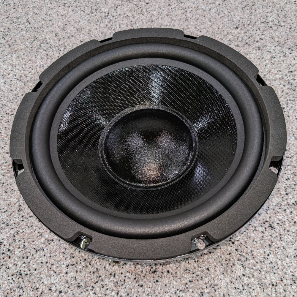
The woofer needs a trim ring and after much time spent getting the 3D printer to print properly again I have my first test print.
The woofer.
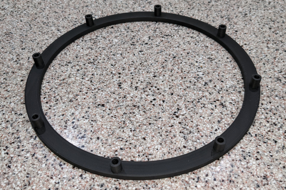
The trim ring.
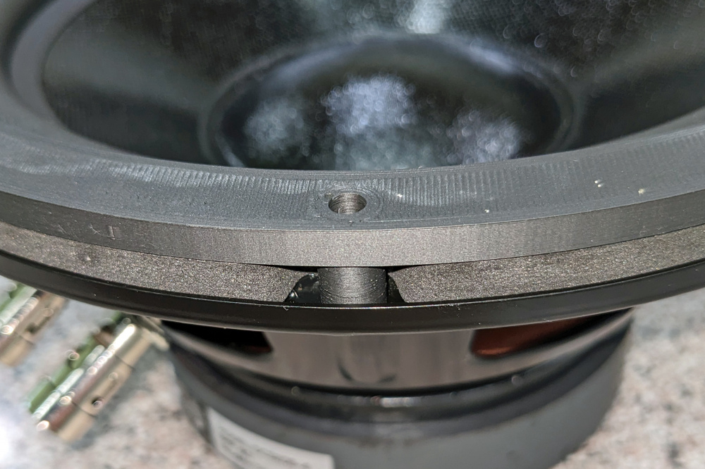
The trim ring installed.
In the past I've built a few speakers with metal grills and woofers with an exposed gasket like this woofer has. I found that the right nylon standoff just fit in the pocket left by the gasket and holds the grill frame flush with the face of the gasket. I just duplicated the standoff dimensions and used the mechanical drawings for the woofer to layout the ring and standoffs in the 3D Cad program. I think I'm going to add some counterbores for the screw heads and put a small bevel on the ring edges. The white on the face of the ring are stress marks from the print sticking to the print bed and will disappear with a little heat from a heat gun.
I started cutting rebates today. I used the wrong bit for the port rebates so the corners don't match the ports I printed. After I verify that the ports are the right lengths, I'll just reprint the ports with corners that match the rebates.
I've finally got a speaker together enough to measure and design the crossovers. I spent a lot of time figuring out why my 3D printer wouldn't print the first layer correctly. There were multiple issues with the main one being a lack of fine control of the z-offset setting. I found that there was a z-offset plugin for the slicer (Cura) which let me dial it in. I'll be reprinting the ports and woofer trim ring to see if I can get better print quality.
The crossover parts are on order and even using non-polar electrolytics for the caps in the low pass section cost $180. Big iron core inductors are pricy. It's the first time I've had to use a LCR across a woofer to tame the low end response.
I might actually have these done in time for Ankeny
Considering the price and availability of ports, I suspect that someone selling end caps that fit over schedule 40 PVC would sell good amount.
And 3d printing just the caps would be a lot faster than whole ports.
@Silver1omo said:
Considering the price and availability of ports, I suspect that someone selling end caps that fit over schedule 40 PVC would sell good amount.
And 3d printing just the caps would be a lot faster than whole ports.
3D printing allows me to fine adjust the diameter of the port which affects the length. You're right that you could probably sell flanges for PVC.
I finally got the crossovers built. Earlier in the thread there's a post about a carefully constructed platform on standoffs to mount the crossovers on. To bad that most of the crossover parts were too tall and interfered with the ports and the size was way too small for all the large parts. I ended up putting the crossover on 3 separate pieces of 1/4" ply so I could space them out and give the big coils some separation.
@PWRRYD said:
Did I see that right? 12 mH and 1000 uF?
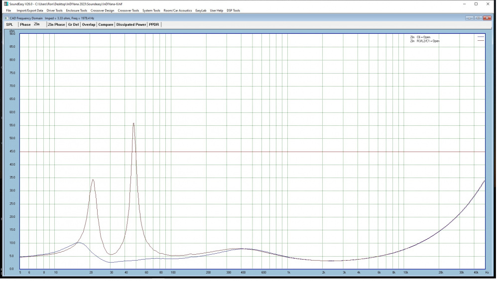
You did. I just couldn't tame the low end with a 50ohm impedance peak at 50hz.
I just finished installing the crossover in one of the cabinets. It was a PITA. It's a good thing I spent many years of my working career assembling things in impossible spaces.
I got to listen to the pair today and I'm impressed. Having an F3 in the low 20's and a decent planar tweeter really works for me. I might have to keep these and put them in the living room.
I still need to reprint the ports and woofer trim rings to fix some cosmetic issues and they'll be ready for Ankeny.
Since I'm using a subwoofer as a regular woofer these will be named the subterfuges. Anyone bringing their InDIYana entry to Ankeny?
Nice job, Ron! Looking good, as usual. I have a couple questions. You printed an extra large enclosure for the GRS PT2522. I have a pair of these and was wondering how low of a crossover frequency you we able to obtain by using this custom enclosure. Also, I was wondering about the 1000uf/12mH/3.6 ohm filter on the woofer. I am not familiar with this technique. Could you explain, in a bit more detail, how the 50 ohm peak at 50Hz was causing a response problem? Thanks.
Since I'm using a subwoofer as a regular woofer these will be named the subterfuges. Anyone bringing their InDIYana entry to Ankeny?
Ron
I was not planning to bring my InDIYana entry (Zonkers) to Iowa. But they are small and I will have enough room to bring them for comparison on Friday night, if that is OK. I'll be playing my Retros on Saturday.
Bill, the large notch is to minimize the driver resonance in the box. If using a large lowpass coil, of minimal DCR, the resonance in combo with said coil will produce a bump in the response. PBN audio and others usually employ a notch of large value to minimize the resonance and bring the bump back to flat. It is not the most inexpensive method, but one of about 4 in the arsenal you can apply.
1- full LCR.
2- larger DCR coil will add more damping to the lowpass and minimize the bump.
3- place a 50 ohm or higher 25W+ resistor across the woofer to somewhat counteract the resonance similar to some tweeter shunt resistors. The resistor will not take off much output level at this high value.
4- use a network similar to that of my EMP build, where a lowpass coil and highpass cap are placed in parallel and series with the driver. If their rolloffs are spread apart enough, the bump is minimized. Some resistance may be needed for balance on the highpass side.
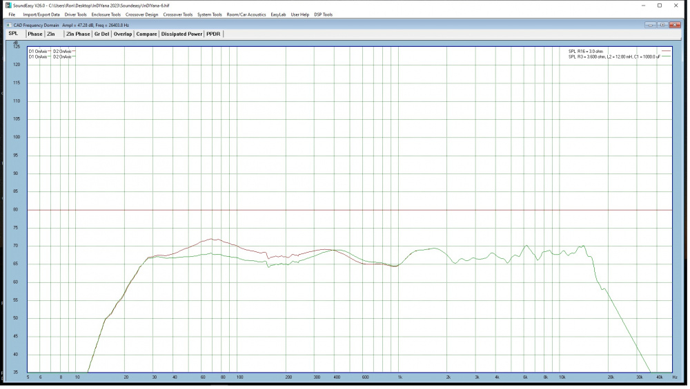
I crossed at 800hz at 24db/oct. This is the response I got using a test baffle that shows that my rear enclosure gives pretty much the same response as having no enclosure. Red is open back. Green is with the enclosure
The RCL across the woofer flattens the impedance and is commonly used on tweeters. I Googled and found that it's also used on woofers. The calculation actually called for a 16mh coil but I found that 12mh got me close enough and that's the largest value that JF stocks. I was getting a large bump in the low end in my sims and found that if I replaced the driver with a 4 ohm resister it would disappear so I knew I was fighting the woofer impedance peak.
This is a sim of the final crossover FR with and without the RCL network.
This is a sim of the woofer impedance with and without the RCL network.
Cool. I think I have seen this response bump problem on a number of my builds, but since I did not know how to address it, the bump remained. Also, it would be very easy to misinterpret this bump as an extended bass shelf alignment, because that is what it tends to look like on your graph. Thanks for the detailed responses. I'll bring the Zonkers along for comparisons.
My 3D printer was giving me grief which seemed to be a problem with the hot end so I just converted the printer to a direct drive extruder which included all new hot end parts. It prints much better now. I wanted to reprint most of the parts I'd printer earlier to improve on the cosmetics. This is the first port after the rebuild.
I've also reprinted the woofer trim rings. The woofers don't have a finished front flange so I printed spacers and a trim ring.
Edit: I think you meant last Spring's entry. I am bringing next Spring's entry, not what you were asking about. Sorry not enough coffee when I posted that.
The question came up on whether there were any distortion measurements for the GRS tweeter crossed at 800hz. I didn't have any because I'd never figured out how to take them with SoundEasy. I upgraded to the the latest version of SE and downloaded the current manual files (all 23 chapters - one chapter at a time - some zipped and some plain PDF). SE has an analog HD extraction system that uses a sin sweep. As you can see from the image you can set the level of the HD plots anywhere you want so it doesn't seem to give you any idea of how far down the distortion is relative to the test signal. Then again I did check a box that adds 40db to the harmonics and added 10db to the signal. I guess that would make these graphs look pretty good. Never having taken HD measurement before I don't know how loud I should be testing at either.
This is the plot with the mic on axis with the tweeter at 1 meter. The distortion at 800hz where the tweeter crosses is no worse than the woofer.
As a comparison I grabbed a Dayton B652 budget 2-way and didn't change any settings. I just placed it tweeter down on top of the Subterfuge and ran the HD test again.
The goals include; getting enough output to swamp the noise floor as this will provide more distinct separation of the HD curves. I usually measure at 90-95dB/1m for the completed systems as they should be able to handle that in most cases. For drivers, I will cap off a tweeter with a 70uF, nothing on the others, and shoot for the same output.
BTW, Ron, those look fantastic! Shame I didn't get to hear them...
Comments
Looks waaay better than my last veneer project.
I'm fine with the white lines. I knew it would end up that way when I saw the veneer. I would prefer a more neutral colored backer and plan to ask the vendor what's up with the white backer. The last batch of walnut was the same way.
That's an HP 334A distortion analyzer in the background. It's been gathering dust for more than 30 years which is criminal. I have no idea if it still works but it is the model with the auto null feature.
Ron
I picked up an HP 330B (1948) that I'm re-building. Those things are built like a tank!
That thing is older than I am.
The finishing is done.
Ron
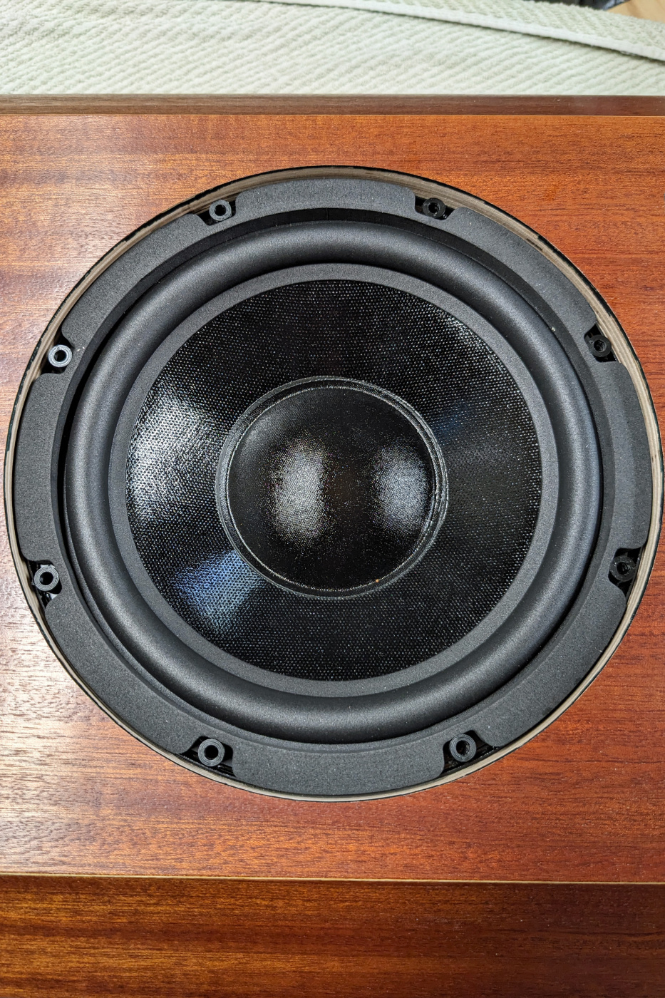
The woofer needs a trim ring and after much time spent getting the 3D printer to print properly again I have my first test print.
The woofer.
The trim ring.
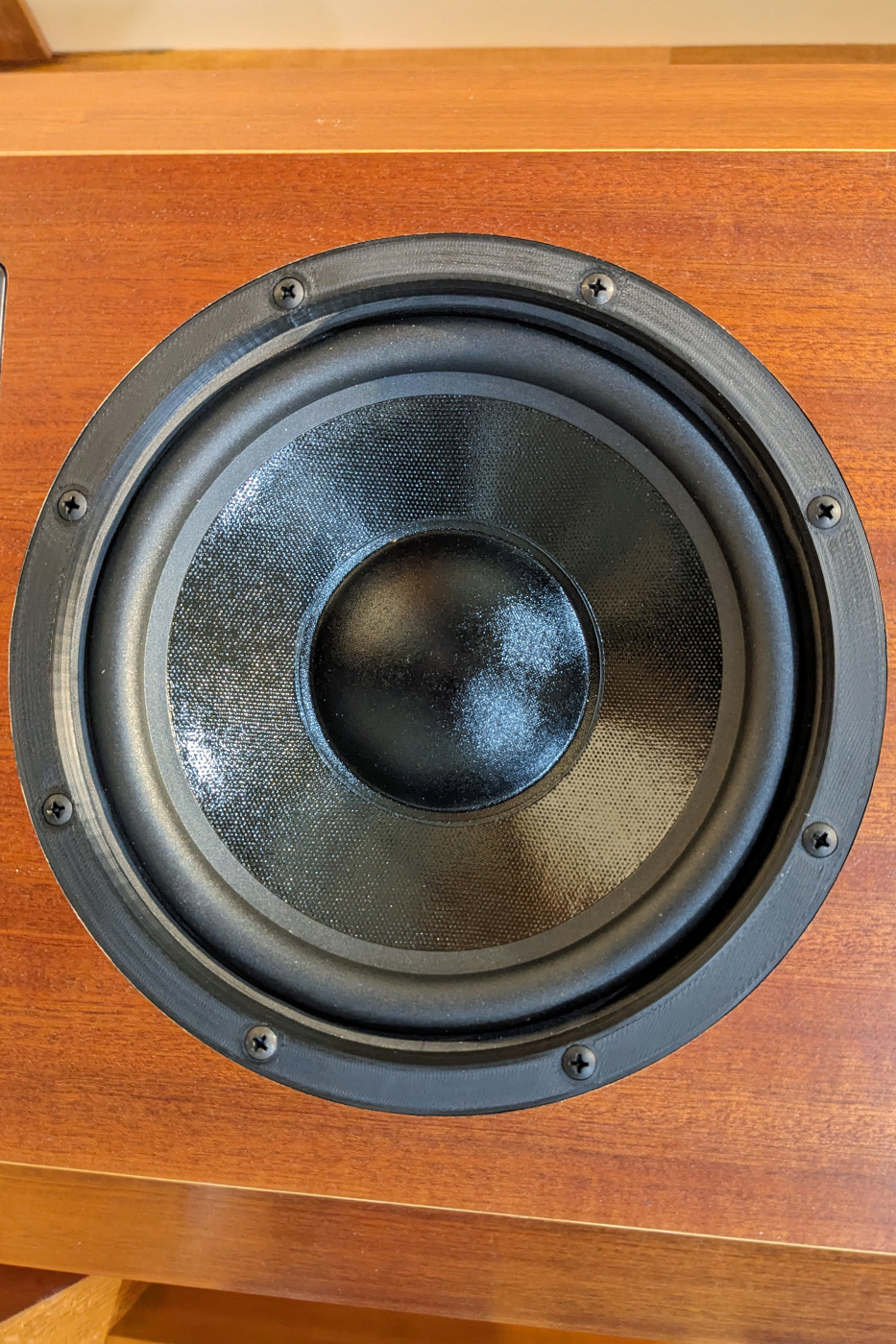
The trim ring installed.
In the past I've built a few speakers with metal grills and woofers with an exposed gasket like this woofer has. I found that the right nylon standoff just fit in the pocket left by the gasket and holds the grill frame flush with the face of the gasket. I just duplicated the standoff dimensions and used the mechanical drawings for the woofer to layout the ring and standoffs in the 3D Cad program. I think I'm going to add some counterbores for the screw heads and put a small bevel on the ring edges. The white on the face of the ring are stress marks from the print sticking to the print bed and will disappear with a little heat from a heat gun.
Ron
I started cutting rebates today. I used the wrong bit for the port rebates so the corners don't match the ports I printed. After I verify that the ports are the right lengths, I'll just reprint the ports with corners that match the rebates.
Ron
I've finally got a speaker together enough to measure and design the crossovers. I spent a lot of time figuring out why my 3D printer wouldn't print the first layer correctly. There were multiple issues with the main one being a lack of fine control of the z-offset setting. I found that there was a z-offset plugin for the slicer (Cura) which let me dial it in. I'll be reprinting the ports and woofer trim ring to see if I can get better print quality.
The crossover parts are on order and even using non-polar electrolytics for the caps in the low pass section cost $180. Big iron core inductors are pricy. It's the first time I've had to use a LCR across a woofer to tame the low end response.
I might actually have these done in time for Ankeny
Ron
Considering the price and availability of ports, I suspect that someone selling end caps that fit over schedule 40 PVC would sell good amount.
And 3d printing just the caps would be a lot faster than whole ports.
3D printing allows me to fine adjust the diameter of the port which affects the length. You're right that you could probably sell flanges for PVC.
Ron
Total control of diameter and length is a real advantage for sure.
Parts came today and I breadboarded a crossover. It measured pretty well and I think it sounded pretty good. I'm looking forward to hearing a pair.
Ron
Very very nice!!
I put a couple coats of Duratex on the bottoms.
I finally got the crossovers built. Earlier in the thread there's a post about a carefully constructed platform on standoffs to mount the crossovers on. To bad that most of the crossover parts were too tall and interfered with the ports and the size was way too small for all the large parts. I ended up putting the crossover on 3 separate pieces of 1/4" ply so I could space them out and give the big coils some separation.
Ron
Did I see that right? 12 mH and 1000 uF?
You did. I just couldn't tame the low end with a 50ohm impedance peak at 50hz.
I just finished installing the crossover in one of the cabinets. It was a PITA. It's a good thing I spent many years of my working career assembling things in impossible spaces.
Ron
nice lighting job too . . .
I got to listen to the pair today and I'm impressed. Having an F3 in the low 20's and a decent planar tweeter really works for me. I might have to keep these and put them in the living room.")
I still need to reprint the ports and woofer trim rings to fix some cosmetic issues and they'll be ready for Ankeny.
Since I'm using a subwoofer as a regular woofer these will be named the subterfuges. Anyone bringing their InDIYana entry to Ankeny?
Ron
Nice job, Ron! Looking good, as usual. I have a couple questions. You printed an extra large enclosure for the GRS PT2522. I have a pair of these and was wondering how low of a crossover frequency you we able to obtain by using this custom enclosure. Also, I was wondering about the 1000uf/12mH/3.6 ohm filter on the woofer. I am not familiar with this technique. Could you explain, in a bit more detail, how the 50 ohm peak at 50Hz was causing a response problem? Thanks.
I was not planning to bring my InDIYana entry (Zonkers) to Iowa. But they are small and I will have enough room to bring them for comparison on Friday night, if that is OK. I'll be playing my Retros on Saturday.
Bill, the large notch is to minimize the driver resonance in the box. If using a large lowpass coil, of minimal DCR, the resonance in combo with said coil will produce a bump in the response. PBN audio and others usually employ a notch of large value to minimize the resonance and bring the bump back to flat. It is not the most inexpensive method, but one of about 4 in the arsenal you can apply.
1- full LCR.
2- larger DCR coil will add more damping to the lowpass and minimize the bump.
3- place a 50 ohm or higher 25W+ resistor across the woofer to somewhat counteract the resonance similar to some tweeter shunt resistors. The resistor will not take off much output level at this high value.
4- use a network similar to that of my EMP build, where a lowpass coil and highpass cap are placed in parallel and series with the driver. If their rolloffs are spread apart enough, the bump is minimized. Some resistance may be needed for balance on the highpass side.
InDIYana Event Website
I crossed at 800hz at 24db/oct. This is the response I got using a test baffle that shows that my rear enclosure gives pretty much the same response as having no enclosure. Red is open back. Green is with the enclosure
The RCL across the woofer flattens the impedance and is commonly used on tweeters. I Googled and found that it's also used on woofers. The calculation actually called for a 16mh coil but I found that 12mh got me close enough and that's the largest value that JF stocks. I was getting a large bump in the low end in my sims and found that if I replaced the driver with a 4 ohm resister it would disappear so I knew I was fighting the woofer impedance peak.
This is a sim of the final crossover FR with and without the RCL network.
This is a sim of the woofer impedance with and without the RCL network.
I'd love to hear the Zonkers.
Ron
Cool. I think I have seen this response bump problem on a number of my builds, but since I did not know how to address it, the bump remained. Also, it would be very easy to misinterpret this bump as an extended bass shelf alignment, because that is what it tends to look like on your graph. Thanks for the detailed responses. I'll bring the Zonkers along for comparisons.
Is that a typo?
Try 800hz. Now I feel stupid. I'll fix it.
My 3D printer was giving me grief which seemed to be a problem with the hot end so I just converted the printer to a direct drive extruder which included all new hot end parts. It prints much better now. I wanted to reprint most of the parts I'd printer earlier to improve on the cosmetics. This is the first port after the rebuild.
I've also reprinted the woofer trim rings. The woofers don't have a finished front flange so I printed spacers and a trim ring.
Woofer with spacers.
Woofer with trim ring.
Finished speaker.
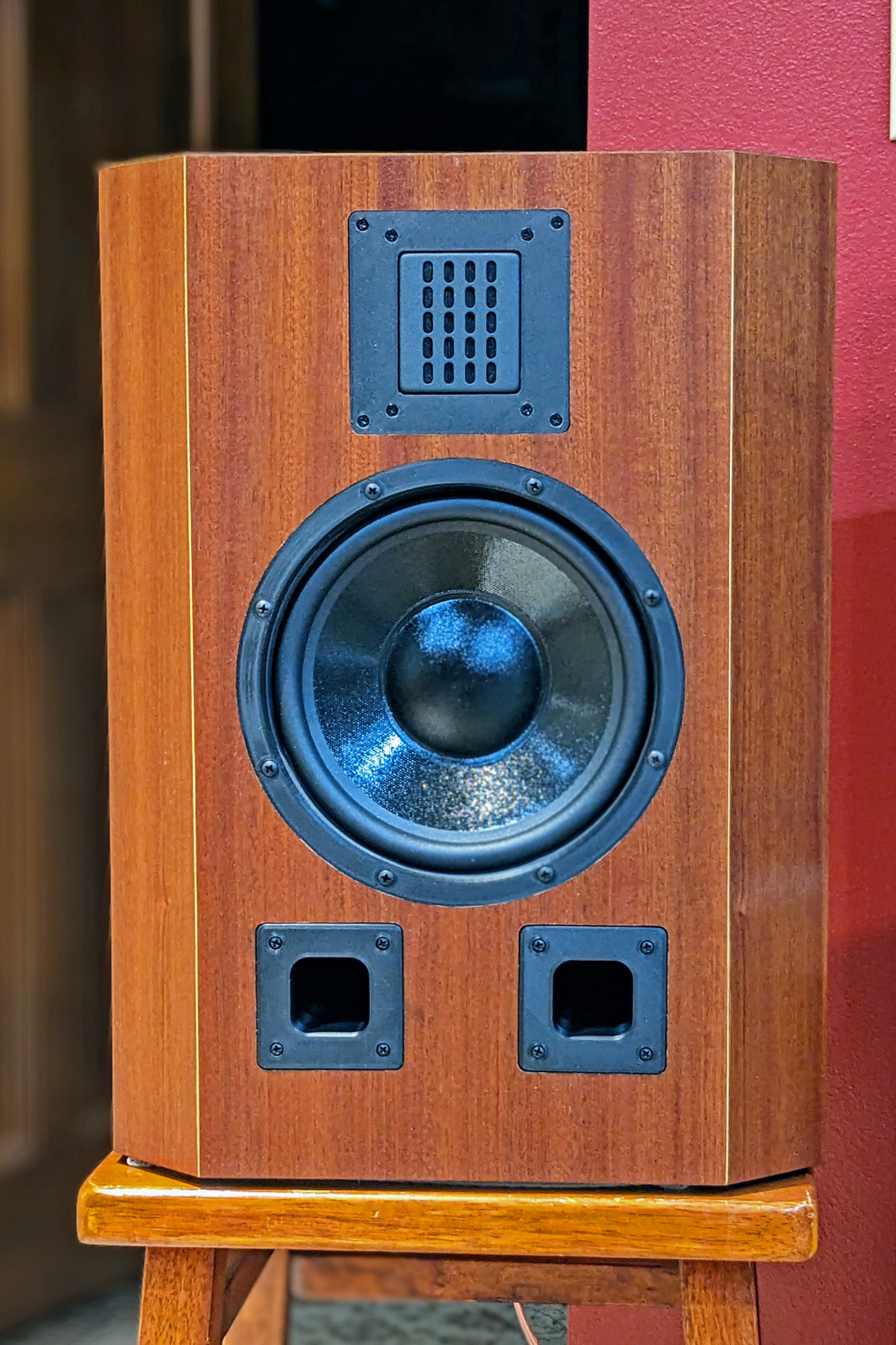
Onward to Ankeny.
Ron
The artistry of your technical skills speaks for its-self in pictures, Ron!!
I will be.
Edit: I think you meant last Spring's entry. I am bringing next Spring's entry, not what you were asking about. Sorry not enough coffee when I posted that.
The question came up on whether there were any distortion measurements for the GRS tweeter crossed at 800hz. I didn't have any because I'd never figured out how to take them with SoundEasy. I upgraded to the the latest version of SE and downloaded the current manual files (all 23 chapters - one chapter at a time - some zipped and some plain PDF). SE has an analog HD extraction system that uses a sin sweep. As you can see from the image you can set the level of the HD plots anywhere you want so it doesn't seem to give you any idea of how far down the distortion is relative to the test signal. Then again I did check a box that adds 40db to the harmonics and added 10db to the signal. I guess that would make these graphs look pretty good. Never having taken HD measurement before I don't know how loud I should be testing at either.
This is the plot with the mic on axis with the tweeter at 1 meter. The distortion at 800hz where the tweeter crosses is no worse than the woofer.
As a comparison I grabbed a Dayton B652 budget 2-way and didn't change any settings. I just placed it tweeter down on top of the Subterfuge and ran the HD test again.
This was the setup.
Ron
The goals include; getting enough output to swamp the noise floor as this will provide more distinct separation of the HD curves. I usually measure at 90-95dB/1m for the completed systems as they should be able to handle that in most cases. For drivers, I will cap off a tweeter with a 70uF, nothing on the others, and shoot for the same output.
BTW, Ron, those look fantastic! Shame I didn't get to hear them...
InDIYana Event Website
Thanks for the input. I'll try to crank them up today and remeasure.
The winner from InDIYana was in Ankeny and I could hear why his speakers came in first.