Thanks Bill! That was a very interesting video and it explains a lot. I see these circuits all the time in old receivers and most people describe them as regulators. Some are regulators that use a Zener diode for a fixed reference in one transistor that feeds the base of the pass transistor. But some are just as he described when using a single transistor. I might try this with a pulled 2SD313 and see what happens. I'll still need to drop ~4 volts, so may end up following that section with a 7812. They are cheap & simple to deploy.
I have used LM7812 regulators for DC filament supplies on pramps too. They work extremely well (super quiet without a ton of filter capacitance) and the tubes don't give a hoot about being fed 0.3 Vdc less.
I tried to get a capacitance multiplier to work, but didn’t have any luck. But adding just a 1000uf cap and LM7812 does the job nicely. I also learned from from EEVblog that my technique for measuring ripple was causing issues. Now that I’ve learned how to do it the correct way, I’m seeing consistent readings.
I recently bought a Siglent SDS1052DL+ when I found one on clearance and it has an"auto" feature that makes life easy. I wouldn't be surprised if your Rigol had a similar feature.
@Tom_S said:
I tried to get a capacitance multiplier to work, but didn’t have any luck. But adding just a 1000uf cap and LM7812 does the job nicely. I also learned from from EEVblog that my technique for measuring ripple was causing issues. Now that I’ve learned how to do it the correct way, I’m seeing consistent readings.
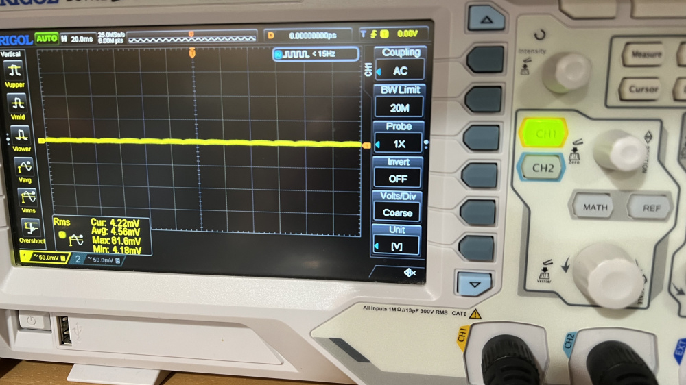
Can’t complain about 4.5mv of ripple.
Excellent! 600mv down to 4.5mV with only 2 parts (a factor of 133). That is quite an improvement!
As an aside, when I purchased my Tektronix TBS 1052B digital oscilloscope a few years ago, it came with a really nice set of probes. And I was always wondering what those small, little paper clip looking things were that came with the probes. Now I can see what they are used for. Good thing I did not throw them away.
Yeah - I had no clue what those were either. I think the ripple from before was multiplied by using the wrong technique. I cobbled that circuit into the preamp & I’m still hearing some hum and noise. I have a feeling Craig is right about the B+ circuit. I have a plan, but it uses another board. More later!
I only know that from personal experience. I tried to use a transformer with a 140 VAC plate winding and a voltage doubler circuit, then C-R-C filter to hit a B+ of 180 Vdc for a line stage project. Big time B+ ripple and noise city. The correct transformer with a SS fullwave bridge then a simple C-R-C filter was 100 times cleaner/quieter.
I'm still waiting for my Amazon order, but since it was so cheap, I ordered 2 kits instead of 1, figuring that if a few parts were dodgy or out of tolerance, I could quickly swap out the suspect parts from the other kit. But now I am thinking that, since I will have two PCB boards, why not use one board for the power supply parts and the other board for the signal path parts. Then feed the signal path board with highly filtered DC voltages only, keeping all forms of AC away from the signal path wiring. How does that sound?
Some good news - I figured out the hum & noise issue. It wasn't the B+ supply. It turned out to be a grounding problem on my new audio interface. I had been using some XLR balanced cables that lifted the shields from the RCA jacks and those were creating a ground loop through my laptop's power supply. I must have been getting some switching garbage mixed in there too. I substituted regular RCA cables on the preamp's inputs and hum is way down now. I'm now seeing THD numbers of .21% in one channel and .12% in the other. Still have too much gain, so I'll do the feedback and cathode cap mods later today.
Bill - I like your idea. I had set up a cheap Chinese LM317/LM337 board last night as a test. I fed it from two 12v-0-12v transformers and it worked like a charm. If I go that route, I'll order a 48v CT Hammond transformer from Mouser. They are only $15.
@Tom_S said:
Bill - I like your idea. I had set up a cheap Chinese LM317/LM337 board last night as a test. I fed it from two 12v-0-12v transformers and it worked like a charm. If I go that route, I'll order a 48v CT Hammond transformer from Mouser. They are only $15.
Ok, let me see if I am following you. Would this eliminate the need for the voltage doubler circuit? 48v CT going into a full-wave bridge could be configured to produce approx plus and minus 28VDC, replacing the existing voltage doubler circuitry.
Exactly! I'm not sure if this particular tube is really worth all the effort, but it might turn out to be a little gem of a preamp. I've invested far more time & money in other hobby related projects over the years and this stuff keeps me out of the bars at night.
Ouch! I’ll bet that smelled up the house. I’m guessing you have played around with these kits. If so, what all did you try - besides running the B+ higher?
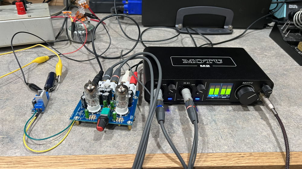
I got a bag of lm317 reg boards today. Just added a 1n4007 and 1000uf cap on the input, powered from the other secondary winding to run the heaters. Listening to it now on headphones via the MOTU interface. Pretty good and the hum is barely audible.
COVID claimed almost all my sense of smell so burnt electronics don't bother me like they used to. Cooked a 500watt power supply this last week and couldn't smell a thing while it was on fire (never popped a fuse ). I do pay a bit more attention to fire alarm maintenance than I used to.
I wasn't measuring the voltage when this preamp popped but I think I was only at the threshold not over. I might still have the board if someone really wants it.
That bites! I hope you get your sense of smell back.
I just checked and my B+ voltages are +/- ~35v. 14vac coming in at the jack. I don't think the little bit of current from this circuit is loading the power transformer enough. I have it on a separate sec winding that's not supplying the heaters. Maybe that's not a bad thing? I'll have to look at the tube spec sheet tomorrow.
I still have too much gain, but the THD dropped with the mods. Frequency response looks strange, like there's ringing as frequency rises. Might have to poke at with the scope tomorrow before the kids come over.
I forgot to change the grid resistors to 22k. That dropped the gain to just over 10dB. Distortion also went down. Ringing in Arta is gone now. I think the garage and noise on the left channel may be due to the AC power running right next to the input traces on PCB. Could also be a bad tube. I have more coming.
While I'm waiting for my boards, I did some heater supply prototyping with my Radio Shack transformer. Got the ripple down to 26mv peak to peak (0.2%) and 2.19mv rms (.017%) with 12.6vdc at the output. The last two RC stages of this heater circuit will be soldered directly on the two small PCB boards, replacing the half-wave rectifier diodes and C13 (470uF) caps. The full-wave bridge and two larger caps & resistors will go on a small homebrew PCB, right next to the Radio Shack transformer. Then I will need to use a separate transformer for the B+ circuit. I found a transformer looks like it will work for the B+, but I still need to prototype it to be sure.
For the filament supply I think I'd go with a full wave bridge, an LM7812 and the two caps. Simple, cheap, and super effective. For the B+ definitely a transformer with a higher secondary voltage followed by a C-R-C-R-C fiilter.
@PWRRYD said:
For the filament supply I think I'd go with a full wave bridge, an LM7812 and the two caps. Simple, cheap, and super effective. For the B+ definitely a transformer with a higher secondary voltage followed by a C-R-C-R-C fiilter.
Craig, I have a 7812 on hand. I'll re-arrange my breadboard with the full wave bridge, two caps, and 7812. I'll measure it with my scope to see how this config compares in terms of output ripple. For the B+, I have an old, unused transformer with a center tapped 44.5vac - 0 - 44.5vac secondary. I can use a full-wave bridge on one-half of the secondary to get 62 volts, then use a C-R-C-R-C filter to slowly drop this to about 56vdc. But I need to know how much current is flowing from plate to cathode through both 6J1 tubes before I can accurately breadboard this. Each one is probably conducting about 5ma, so two tubes would be about 10ma @ 56vdc. But I am guessing. I'll have to wait until I get my kits to check this out. With both tubes running, I would simply measure the voltage drop across the 4.7k plate resistor (R15 or R20), calculate the current through just one tube, then double this figure for both tubes. Then I can accurately breadboard the voltage drops through the C-R-C-R-C filter to see if this will work out.
Yes that will work for sure. Or you can measure the voltage across the cathode resistor and get the same current per tube (grid current is microamps so plate ~= cathode current).
Comments
Thanks Bill! That was a very interesting video and it explains a lot. I see these circuits all the time in old receivers and most people describe them as regulators. Some are regulators that use a Zener diode for a fixed reference in one transistor that feeds the base of the pass transistor. But some are just as he described when using a single transistor. I might try this with a pulled 2SD313 and see what happens. I'll still need to drop ~4 volts, so may end up following that section with a 7812. They are cheap & simple to deploy.
I have used LM7812 regulators for DC filament supplies on pramps too. They work extremely well (super quiet without a ton of filter capacitance) and the tubes don't give a hoot about being fed 0.3 Vdc less.
I tried to get a capacitance multiplier to work, but didn’t have any luck. But adding just a 1000uf cap and LM7812 does the job nicely. I also learned from from EEVblog that my technique for measuring ripple was causing issues. Now that I’ve learned how to do it the correct way, I’m seeing consistent readings.
Can’t complain about 4.5mv of ripple.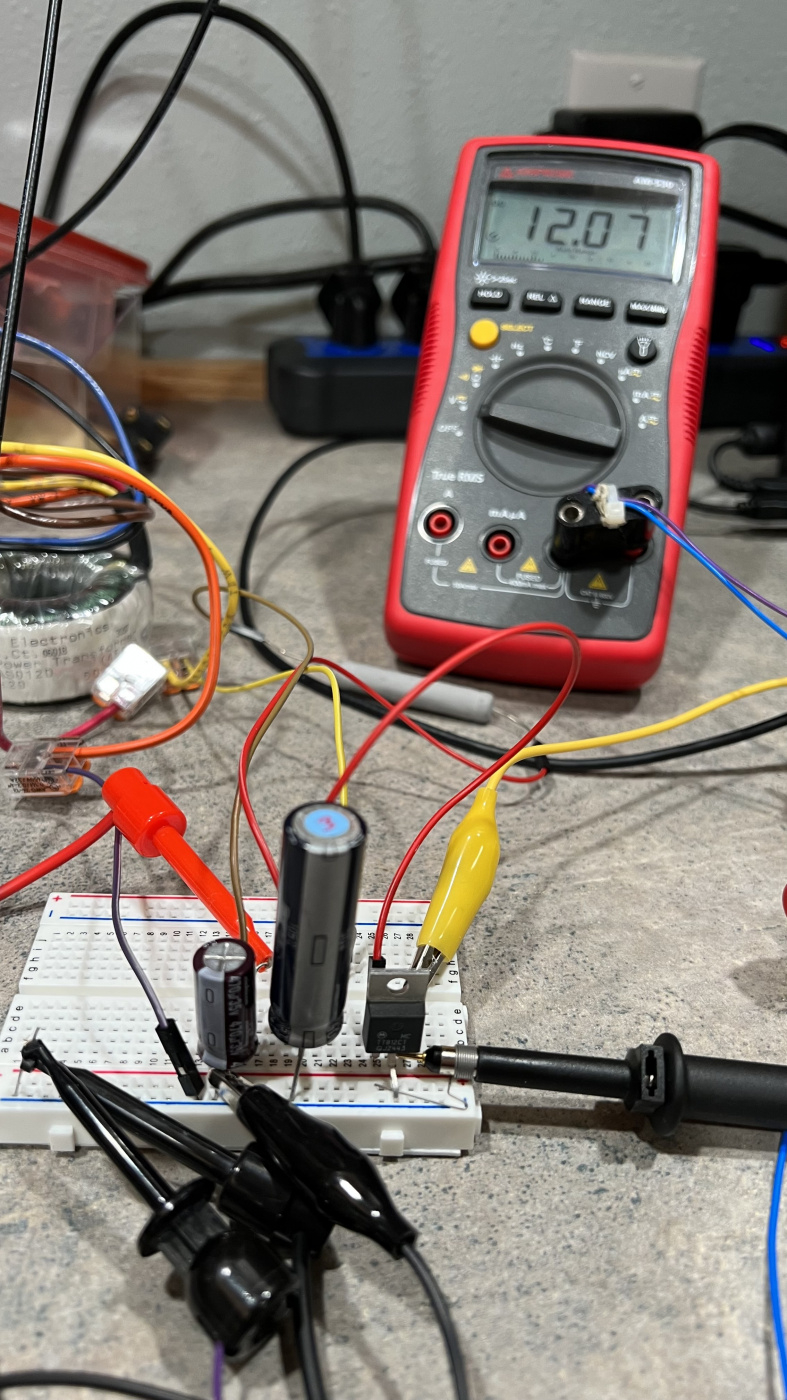
Which Rigol is that?
It's a DS1102Z-E. I bought it during the pandemic and I'm still figuring it out.
I'm with you Tom, I struggle with the new digital scopes.
I recently bought a Siglent SDS1052DL+ when I found one on clearance and it has an"auto" feature that makes life easy. I wouldn't be surprised if your Rigol had a similar feature.
Excellent! 600mv down to 4.5mV with only 2 parts (a factor of 133). That is quite an improvement!")
As an aside, when I purchased my Tektronix TBS 1052B digital oscilloscope a few years ago, it came with a really nice set of probes. And I was always wondering what those small, little paper clip looking things were that came with the probes. Now I can see what they are used for. Good thing I did not throw them away.
Yeah - I had no clue what those were either. I think the ripple from before was multiplied by using the wrong technique. I cobbled that circuit into the preamp & I’m still hearing some hum and noise. I have a feeling Craig is right about the B+ circuit. I have a plan, but it uses another board. More later!
I only know that from personal experience. I tried to use a transformer with a 140 VAC plate winding and a voltage doubler circuit, then C-R-C filter to hit a B+ of 180 Vdc for a line stage project. Big time B+ ripple and noise city. The correct transformer with a SS fullwave bridge then a simple C-R-C filter was 100 times cleaner/quieter.
I'm still waiting for my Amazon order, but since it was so cheap, I ordered 2 kits instead of 1, figuring that if a few parts were dodgy or out of tolerance, I could quickly swap out the suspect parts from the other kit. But now I am thinking that, since I will have two PCB boards, why not use one board for the power supply parts and the other board for the signal path parts. Then feed the signal path board with highly filtered DC voltages only, keeping all forms of AC away from the signal path wiring. How does that sound?
Some good news - I figured out the hum & noise issue. It wasn't the B+ supply. It turned out to be a grounding problem on my new audio interface. I had been using some XLR balanced cables that lifted the shields from the RCA jacks and those were creating a ground loop through my laptop's power supply. I must have been getting some switching garbage mixed in there too. I substituted regular RCA cables on the preamp's inputs and hum is way down now. I'm now seeing THD numbers of .21% in one channel and .12% in the other. Still have too much gain, so I'll do the feedback and cathode cap mods later today.
Bill - I like your idea. I had set up a cheap Chinese LM317/LM337 board last night as a test. I fed it from two 12v-0-12v transformers and it worked like a charm. If I go that route, I'll order a 48v CT Hammond transformer from Mouser. They are only $15.
Ok, let me see if I am following you. Would this eliminate the need for the voltage doubler circuit? 48v CT going into a full-wave bridge could be configured to produce approx plus and minus 28VDC, replacing the existing voltage doubler circuitry.
Exactly! I'm not sure if this particular tube is really worth all the effort, but it might turn out to be a little gem of a preamp. I've invested far more time & money in other hobby related projects over the years and this stuff keeps me out of the bars at night.")
Here's the board I had in the parts bin -
https://www.amazon.com/KNACRO-Adjustable-Voltage-Regulator-Supply/dp/B0741T2W3G
A huge +1 to that my friend.
Feedback & cathode bypass mods completed.
Beware the caps have zero headroom do not push the voltage anywhere neer their limits. It was kinda fun watching it let the smoke out.
Ouch! I’ll bet that smelled up the house. I’m guessing you have played around with these kits. If so, what all did you try - besides running the B+ higher?
I got a bag of lm317 reg boards today. Just added a 1n4007 and 1000uf cap on the input, powered from the other secondary winding to run the heaters. Listening to it now on headphones via the MOTU interface. Pretty good and the hum is barely audible.
COVID claimed almost all my sense of smell so burnt electronics don't bother me like they used to. Cooked a 500watt power supply this last week and couldn't smell a thing while it was on fire (never popped a fuse ). I do pay a bit more attention to fire alarm maintenance than I used to.
I wasn't measuring the voltage when this preamp popped but I think I was only at the threshold not over. I might still have the board if someone really wants it.
That bites! I hope you get your sense of smell back.
I just checked and my B+ voltages are +/- ~35v. 14vac coming in at the jack. I don't think the little bit of current from this circuit is loading the power transformer enough. I have it on a separate sec winding that's not supplying the heaters. Maybe that's not a bad thing? I'll have to look at the tube spec sheet tomorrow.
I still have too much gain, but the THD dropped with the mods. Frequency response looks strange, like there's ringing as frequency rises. Might have to poke at with the scope tomorrow before the kids come over.
I forgot to change the grid resistors to 22k. That dropped the gain to just over 10dB. Distortion also went down. Ringing in Arta is gone now. I think the garage and noise on the left channel may be due to the AC power running right next to the input traces on PCB. Could also be a bad tube. I have more coming.
While I'm waiting for my boards, I did some heater supply prototyping with my Radio Shack transformer. Got the ripple down to 26mv peak to peak (0.2%) and 2.19mv rms (.017%) with 12.6vdc at the output. The last two RC stages of this heater circuit will be soldered directly on the two small PCB boards, replacing the half-wave rectifier diodes and C13 (470uF) caps. The full-wave bridge and two larger caps & resistors will go on a small homebrew PCB, right next to the Radio Shack transformer. Then I will need to use a separate transformer for the B+ circuit. I found a transformer looks like it will work for the B+, but I still need to prototype it to be sure.
For the filament supply I think I'd go with a full wave bridge, an LM7812 and the two caps. Simple, cheap, and super effective. For the B+ definitely a transformer with a higher secondary voltage followed by a C-R-C-R-C fiilter.
Craig, I have a 7812 on hand. I'll re-arrange my breadboard with the full wave bridge, two caps, and 7812. I'll measure it with my scope to see how this config compares in terms of output ripple. For the B+, I have an old, unused transformer with a center tapped 44.5vac - 0 - 44.5vac secondary. I can use a full-wave bridge on one-half of the secondary to get 62 volts, then use a C-R-C-R-C filter to slowly drop this to about 56vdc. But I need to know how much current is flowing from plate to cathode through both 6J1 tubes before I can accurately breadboard this. Each one is probably conducting about 5ma, so two tubes would be about 10ma @ 56vdc. But I am guessing. I'll have to wait until I get my kits to check this out. With both tubes running, I would simply measure the voltage drop across the 4.7k plate resistor (R15 or R20), calculate the current through just one tube, then double this figure for both tubes. Then I can accurately breadboard the voltage drops through the C-R-C-R-C filter to see if this will work out.
Yes that will work for sure. Or you can measure the voltage across the cathode resistor and get the same current per tube (grid current is microamps so plate ~= cathode current).