Looks like he plotted the load line for 3.66ma/tube. If the transformer you found has dual primaries, you could wire them in series to cut the output in half. I ordered a little Hammond from Mouser, but it won't be here until sometime next week. https://www.mouser.com/ProductDetail/546-187A48
I also realized I don't have any small 12.6v filament transformers in my stash, so I threw one in the order for $11. Even with those transformers, the upgrade parts and the reg boards, I think this project will come in around $75. I'll find some better RCA jacks, a power switch, IEC jack & fuse holder in the parts stash and then think about some kind of case. Starting to think I should just build it point-to-point and skip the PCB, but I don’t think I have any 7 pin sockets.
Oh, I also found a matched pair of JAN 5654 tubes on Amazon for $12.79. We'll see if those end up being counterfeits. Probably rebranded Russian or Chinese tubes...
Thanks for the info. So, 3.66 x 2 = 7.32ma total. 56 volts / .00732 = 7650 ohms. 56 x .00732 = .4099 watts. So, I will need a 1 watt, 7.65K resistor to use as the load in order to accuately breadboard my B+ prototype power supply. I'm not sure if my transformer has a dual primary. I'll have to check.
Not that this is applicable to this particular preamp project but I thought I'd throw this in here for future projects since Radio Shack is gone... consider a door bell transformer from Home Depot, Ace Hardward, etc. They have some that have 3 secondary winding taps. Usually 8, 16, and 24 Vac, and usually around 10 VA. I've seen them as cheap as $13.
I had forgotten about psud2. Haven't used it in years but I see it's still on my desktop machine. Playing around with it - the cap resistance makes a huge difference. If that's the ESR, then the default's are way too high.
Not meaning to clutter up this thread too much more but I bought 10 pcs of these voltage regulator boards on Amazon for about $1.50 each. They work great for tube filament supplies, slowing/quieting 12 Vdc cooling fans, etc. I bought them to run a small 12 V cooling fan on one of my ClassDAmps projects. It's been working perfectly for about 5 years now.
I breadboarded Craig's suggestion using the 7812 12V regulator chip. Ripple at the output is approx 30mv peak to peak and 3.46mv rms. This is roughly the same amount of ripple as the unregulated heater supply that I posted earlier. Either supply will probably work ok, probably would not hear a difference between the two. I added two 0.1 polyester film caps and a reverse current protection diode around the regulator chip.
Since these are indirectly heated cathodes there is no way that tiny bit of ripple on the filaments will be audible. The most important thing with regards to ripple is the B+. Especially in a preamp that has significant gain (10 dB or more).
Both of those approaches look more than good enough, Bill. I got the NOS tubes yesterday, but haven't had a chance to try them yet. They look legit to me.
@Tom_S said:
Looks like he plotted the load line for 3.66ma/tube. If the transformer you found has dual primaries, you could wire them in series to cut the output in half. I ordered a little Hammond from Mouser, but it won't be here until sometime next week. https://www.mouser.com/ProductDetail/546-187A48
I checked my transformer and no, it only has a single 120V primary. It has a center tapped secondary with 44.5V - 0 - 44.5V. So I am going to use one half of the secondary with a full wave bridge to get 62vdc. Drop that to 56vdc with a few stages of RC filtering. Then I plan to reconfigure the boards to run the preamp at 56vdc with respect to ground instead of the current +28, 0, -28vdc arrangement. I'll hook the 470uf 35V caps in series with bleeders so that they can handle a working voltage up to 70vdc instead of 35.
I would use both halves of the secondary windings with two 1N4001 diodes for fullwave rectification. Or better yet two UF4007 ultra fast recovery diodes if you happen to have them on hand.
@PWRRYD said:
I would use both halves of the secondary windings with two 1N4001 diodes for fullwave rectification. Or better yet two UF4007 ultra fast recovery diodes if you happen to have them on hand.
Good idea. This would be a much better way to produce the same output voltages. And this suggestion would also apply to my heater schematics as posted above. Somehow I was thinking, in error, that the voltage would be too high if I used both secondary windings. I forgot to divide by 2 when I was calculating the 2 diode center tapped configuration. Ooops.
You probably want to use the unloaded voltage from the transformer. The circuit just doesn't pull enough current for any reasonable sized transformer to run at rated voltage.
I had also thought about converting to a single supply. I haven't looked at the schematic again to calculate the plate load and cathode resistor values. But wonder if there is any added benefit (like THD/Common Mode Rejection) to running with a dual supply?
But wonder if there is any added benefit (like THD/Common Mode Rejection) to running with a dual supply?
My guess would be that this was the result of making it so that they could very inexpensively boost a simple 12vac input all the way up to 60vdc. A simple voltage doubler would only get you up to 30vdc or so. That would not be high enough to properly bias the tubes. So they stacked two voltage doublers into a voltage quadrupler configuration. But this resulted in a dual supply at the output. Just guessing, there could be other ways to cheaply boost 12vac up to 60vdc. I do not know.
I do see one possible downside to this +/- supply design that was brought up in the DIYAudio thread. Since the grid is referenced to the negative supply, any noise or ripple on that supply line could be amplified along with the audio signal.
@Tom_S said:
You probably want to use the unloaded voltage from the transformer. The circuit just doesn't pull enough current for any reasonable sized transformer to run at rated voltage.
There were no voltage output markings on the xformer. The 44.5 - 0 - 44.5vac is what I measure with no load. So I should be good to go. It was from an old, burned out Panasonic power amp and is much bigger than I really need at about 350VA or so.
With something that big, you'll never have to worry if it's starved for current!
Home for lunch and my Mouser order showed up. This little Hammond is only rated for 50ma, but that should be more than enough. I wanted to keep them small and cheap. The filament transformer is actually a little larger and rated for 350ma.
Awesome! So now you can start tube rolling. You're way ahead of me. I'm still waiting on my Amazon order. I'll more than likely have both of my DC power supplies and my cabinet completely finished before my kits arrive. I'm putting my project in an old, gutted out Panasonic amplifier cabinet, with the transformers and preamp boards separated by about 13 inches. What are you planning to use for a cabinet? Will you be mounting the power supplies in a separate chassis?
Wow, your kits must be taking the long way around. I wonder if they ran out of stock from one of the warehouses and they are being shipped from somewhere else? Either that, or they were on a truck that was in an accident and they are still sorting things out.
I have a small case that was some kind computer or medical display device that's been sitting on the shelf for years. It's not very big, so I'm hoping I can fit everything in there with no issues. I might have to make some kind of shielded area for the power supply.
I ordered 2 kits on 11/15. Just checked Amazon tracking. Says it was shipped on 11/16 via free USPS shipping (not UPS). The expected delivery date is listed as Nov 29 to Dec 12. Probably not a good thing when they give you a 2 week range for the delivery date!
Comments
Looks like he plotted the load line for 3.66ma/tube. If the transformer you found has dual primaries, you could wire them in series to cut the output in half. I ordered a little Hammond from Mouser, but it won't be here until sometime next week.
https://www.mouser.com/ProductDetail/546-187A48
I also realized I don't have any small 12.6v filament transformers in my stash, so I threw one in the order for $11. Even with those transformers, the upgrade parts and the reg boards, I think this project will come in around $75. I'll find some better RCA jacks, a power switch, IEC jack & fuse holder in the parts stash and then think about some kind of case. Starting to think I should just build it point-to-point and skip the PCB, but I don’t think I have any 7 pin sockets.
Oh, I also found a matched pair of JAN 5654 tubes on Amazon for $12.79. We'll see if those end up being counterfeits. Probably rebranded Russian or Chinese tubes...
Thanks for the info. So, 3.66 x 2 = 7.32ma total. 56 volts / .00732 = 7650 ohms. 56 x .00732 = .4099 watts. So, I will need a 1 watt, 7.65K resistor to use as the load in order to accuately breadboard my B+ prototype power supply. I'm not sure if my transformer has a dual primary. I'll have to check.
Not that this is applicable to this particular preamp project but I thought I'd throw this in here for future projects since Radio Shack is gone... consider a door bell transformer from Home Depot, Ace Hardward, etc. They have some that have 3 secondary winding taps. Usually 8, 16, and 24 Vac, and usually around 10 VA. I've seen them as cheap as $13.
Neat PS desiger, if you've never heard of it.
It works ok, if you know what kinda load you'll be driving.
https://www.duncanamps.com/psud2/
psud2 works pretty good but you have to be careful how you set up the simulator parameters. It's kinda buggy like that.
I had forgotten about psud2. Haven't used it in years but I see it's still on my desktop machine. Playing around with it - the cap resistance makes a huge difference. If that's the ESR, then the default's are way too high.
Did I do this right?
Yeah, I used the ESR. If you're meter offers, use it's lower setting, usually 120Hz.
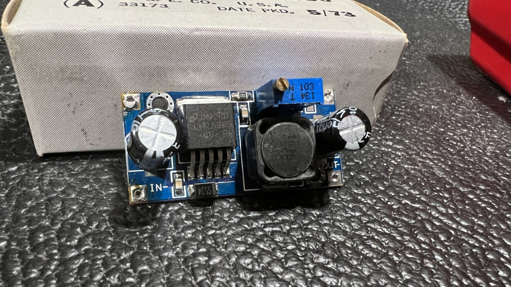
Not meaning to clutter up this thread too much more but I bought 10 pcs of these voltage regulator boards on Amazon for about $1.50 each. They work great for tube filament supplies, slowing/quieting 12 Vdc cooling fans, etc. I bought them to run a small 12 V cooling fan on one of my ClassDAmps projects. It's been working perfectly for about 5 years now.
Found them:
https://www.amazon.com/LM2596-Converter-Module-Supply-1-23V-30V/dp/B008BHBEE0
Their performance is top notch. I can't understand how they can sell something like this for $1.50 each!
No worries! The more things like that, the better. I do like those better than the ones I bought. Those have a lower profile and more filtering.
I breadboarded Craig's suggestion using the 7812 12V regulator chip. Ripple at the output is approx 30mv peak to peak and 3.46mv rms. This is roughly the same amount of ripple as the unregulated heater supply that I posted earlier. Either supply will probably work ok, probably would not hear a difference between the two. I added two 0.1 polyester film caps and a reverse current protection diode around the regulator chip.
Since these are indirectly heated cathodes there is no way that tiny bit of ripple on the filaments will be audible. The most important thing with regards to ripple is the B+. Especially in a preamp that has significant gain (10 dB or more).
Both of those approaches look more than good enough, Bill. I got the NOS tubes yesterday, but haven't had a chance to try them yet. They look legit to me.
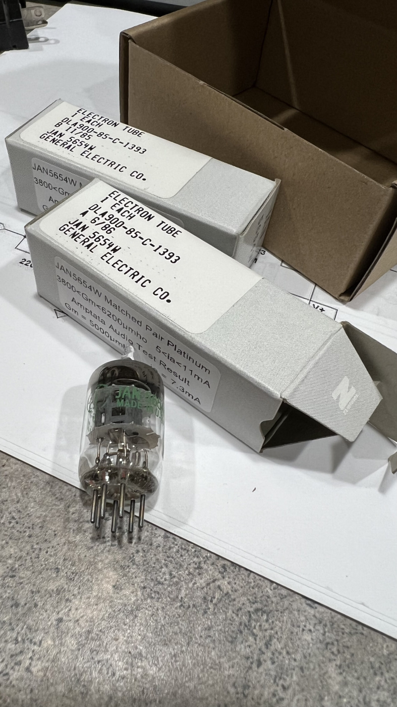
And look what I found in my box of misc arduino parts!
Gotta love General Electric JAN tubes!
Looking at the date codes... 6/86 was the month/year I graduated HS. Hard to believe they were still manufacturing tubes.
I checked my transformer and no, it only has a single 120V primary. It has a center tapped secondary with 44.5V - 0 - 44.5V. So I am going to use one half of the secondary with a full wave bridge to get 62vdc. Drop that to 56vdc with a few stages of RC filtering. Then I plan to reconfigure the boards to run the preamp at 56vdc with respect to ground instead of the current +28, 0, -28vdc arrangement. I'll hook the 470uf 35V caps in series with bleeders so that they can handle a working voltage up to 70vdc instead of 35.
I would use both halves of the secondary windings with two 1N4001 diodes for fullwave rectification. Or better yet two UF4007 ultra fast recovery diodes if you happen to have them on hand.
Good idea. This would be a much better way to produce the same output voltages. And this suggestion would also apply to my heater schematics as posted above. Somehow I was thinking, in error, that the voltage would be too high if I used both secondary windings. I forgot to divide by 2 when I was calculating the 2 diode center tapped configuration. Ooops.
You probably want to use the unloaded voltage from the transformer. The circuit just doesn't pull enough current for any reasonable sized transformer to run at rated voltage.
I had also thought about converting to a single supply. I haven't looked at the schematic again to calculate the plate load and cathode resistor values. But wonder if there is any added benefit (like THD/Common Mode Rejection) to running with a dual supply?
My guess would be that this was the result of making it so that they could very inexpensively boost a simple 12vac input all the way up to 60vdc. A simple voltage doubler would only get you up to 30vdc or so. That would not be high enough to properly bias the tubes. So they stacked two voltage doublers into a voltage quadrupler configuration. But this resulted in a dual supply at the output. Just guessing, there could be other ways to cheaply boost 12vac up to 60vdc. I do not know.
I do see one possible downside to this +/- supply design that was brought up in the DIYAudio thread. Since the grid is referenced to the negative supply, any noise or ripple on that supply line could be amplified along with the audio signal.
There were no voltage output markings on the xformer. The 44.5 - 0 - 44.5vac is what I measure with no load. So I should be good to go. It was from an old, burned out Panasonic power amp and is much bigger than I really need at about 350VA or so.
With something that big, you'll never have to worry if it's starved for current!
Home for lunch and my Mouser order showed up. This little Hammond is only rated for 50ma, but that should be more than enough. I wanted to keep them small and cheap. The filament transformer is actually a little larger and rated for 350ma.
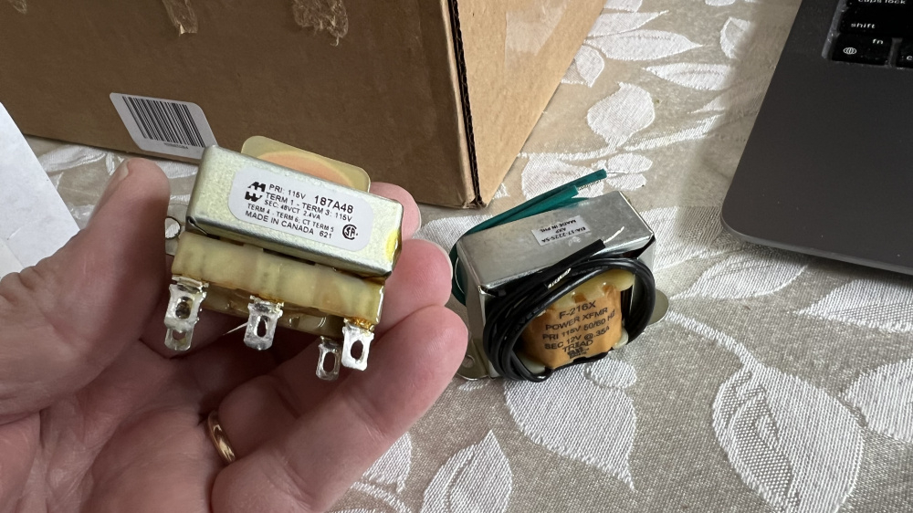
Cool Tom! That xformer looks tiny but is the perfect size for this line-stage/preamp project.
Cobbled this together - both DC supplies and not a trace of hum!
Awesome! So now you can start tube rolling. You're way ahead of me. I'm still waiting on my Amazon order. I'll more than likely have both of my DC power supplies and my cabinet completely finished before my kits arrive. I'm putting my project in an old, gutted out Panasonic amplifier cabinet, with the transformers and preamp boards separated by about 13 inches. What are you planning to use for a cabinet? Will you be mounting the power supplies in a separate chassis?
Wow, your kits must be taking the long way around. I wonder if they ran out of stock from one of the warehouses and they are being shipped from somewhere else? Either that, or they were on a truck that was in an accident and they are still sorting things out.
I have a small case that was some kind computer or medical display device that's been sitting on the shelf for years. It's not very big, so I'm hoping I can fit everything in there with no issues. I might have to make some kind of shielded area for the power supply.
I ordered 2 kits on 11/15. Just checked Amazon tracking. Says it was shipped on 11/16 via free USPS shipping (not UPS). The expected delivery date is listed as Nov 29 to Dec 12. Probably not a good thing when they give you a 2 week range for the delivery date!