Site Links
Howdy, Stranger!
It looks like you're new here. If you want to get involved, click one of these buttons!
Quick Links
Categories
In this Discussion
Who's Online (0)
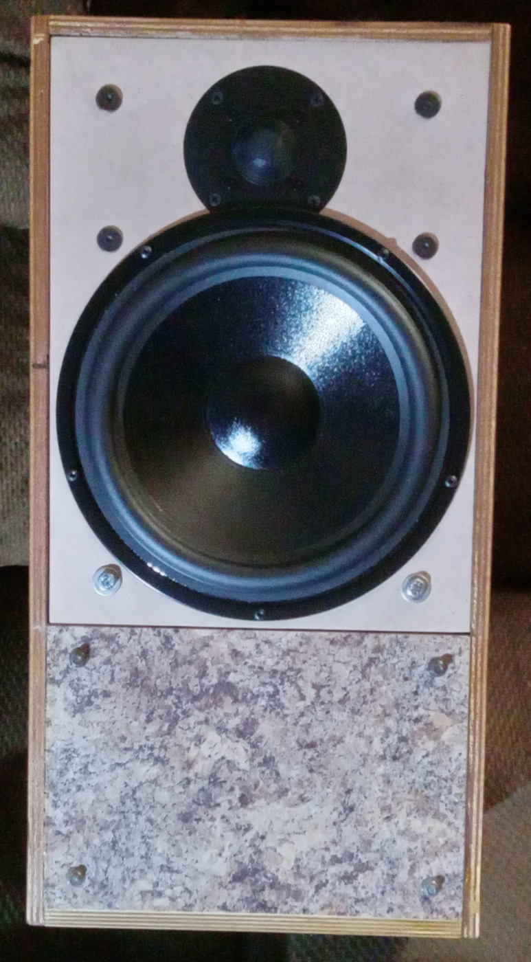
Pangolins, a 10" 2way...

I've had these RST28F B-stock tweeters that I fixed for a while now. I've wanted to do a larger woofer 2way also for a bit, kinda in the aesthetic vein of the Orangutan 0/93. I got to thinking about the Zingers, and thought the SD270A-88 might be a good candidate. The spec FR looks like it could work.
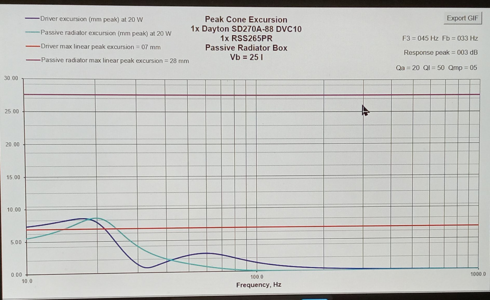
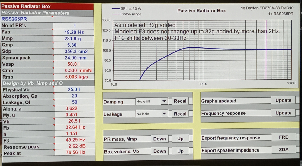
Thus far I've measured the SD270A-88 in parallel for T/S, and modeled the 25ltr MonkeyBox (used first in my Opaz) with the RSS265PR. I finally have the threaded inserts installed too. The tentative F3/10 are 45/30, with about a 2dB bump in the 70-80Hz range right where it matters.
The response looks like that of a Pangolin foraging for grubs and insects to me, and since the DeVore is named after an animal, I said, "why not?" The fact it's an endangered animal calls attention, and that also equates with the 10" 2way premise also being currently nonprevalent. I plan on using the second coil as the BSC compensation, so it is wired as a 2.5way, but with only 2 drivers.
I'm going to use the same kind of FR contouring I used in the Zingers so there will not be a peak in the directivity. No waveguide required, and easy to build. Using the overlapped arrangement like in the Zingers lends well to a 7" CTC. That is pretty good for a woofer that large at a frame radius of 5.5". Without the overlap, typical CTC would likely be between 7.5-8". Wavelength of 7" = 1937Hz. Depending on when the woofer starts to beam, this gives some leeway.
More to come....


Comments
Very interesting/clever concept using the 2nd coil in that way.
I thought everyone here disliked the RST28F?
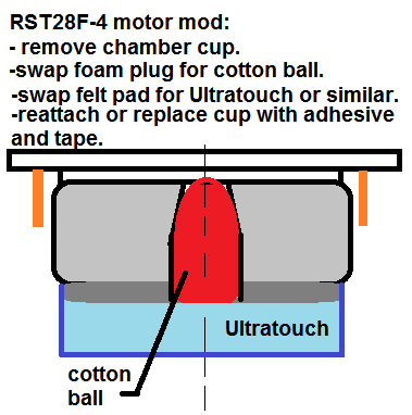
Let's hope since I had to fix them that they sound better than normal. I am not normally in the camp that prefers them either. When I fixed them due to mfr QC impedance issues, I; added a different back-cup, replaced the foam under the dome with a cotton ball, changed the damping in the cup with Denim cotton, and a layer of wool batting against the backplate. These are not the usual RST28F. I will post a drawing of what I did in the near future.
InDIYana Event Website
I used a 1" cotton ball.
InDIYana Event Website
I'm interested in your findings with the mods to the RST28F as I have a pair here I would like to use in the future due to it's caged dome [protection].
Probably should have linked the original thread anyway...
https://techtalk.parts-express.com/forum/tech-talk-forum/1417345-mwaf-contestants-b-stock-rst28f-4-info
InDIYana Event Website
Are these mods actually able to lower 3rd order HD by 20 Db as [I read] the graphs indicated in your ^ link, Wolf?
That is amazing if true . . .
From their previous poor assembly, yes. Their impedances were absolute garbage before I modded them. From the way they should have been and a lot closer to spec, likely not.
InDIYana Event Website
Cool project! I like the name and the concept...
I have found that adding damping behind a driver can smooth response but can also reduce detail. Have you observed this with the tweeter?
I haven't even done any listening with them yet. However, its no different than eliminating the box sound from the woofer cabinet by using damping. Hollow boxes sound awful.
InDIYana Event Website
I 100% agree. I'd always be willing to give up a dB or few Hz of F3 not to have that hollow box sound.
Did some fiddling, measuring at a half meter, on the tweeter axis. I pulled out my multitapped coil with 2.0mH to 10mH in half millihenry steps. I also worked on piecing together a notch to tame the breakup. No modeling, just doing empirical changes.
Basics...
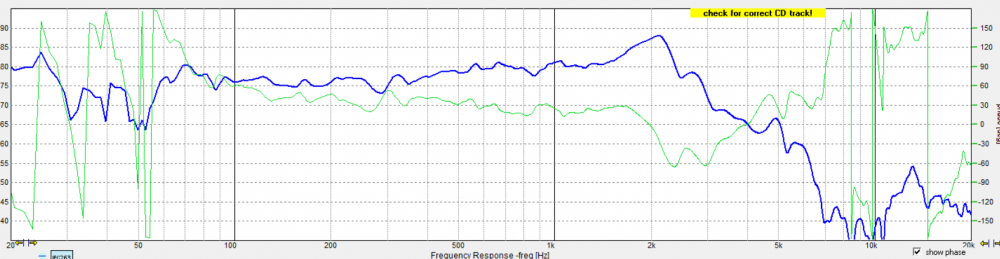
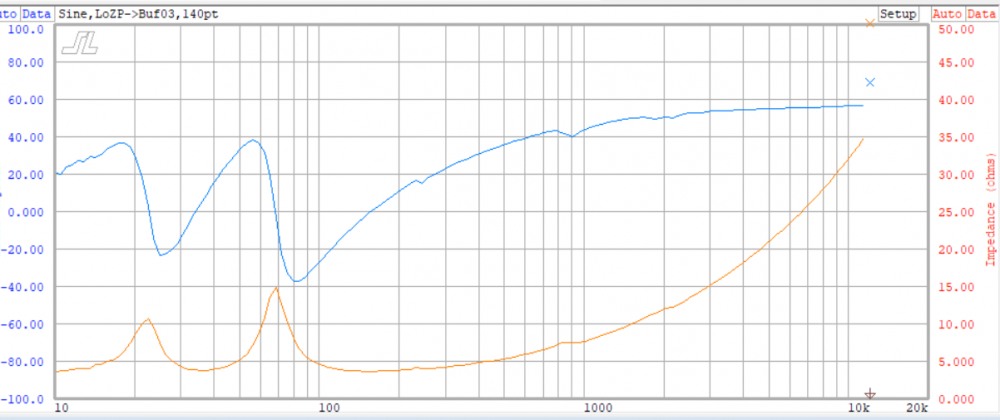
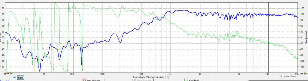
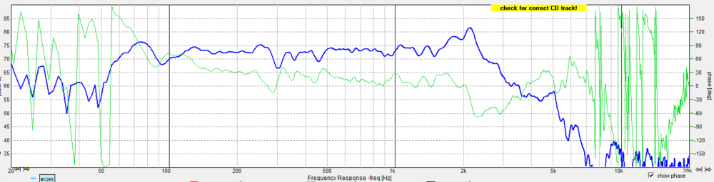
Single coil on woofer axis:
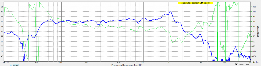
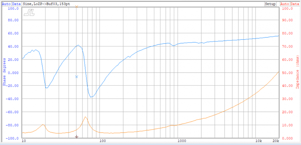
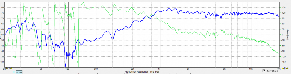
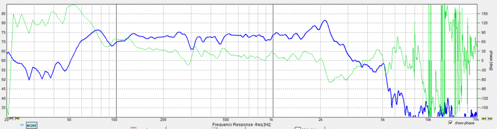
Coils in parallel on woofer axis:
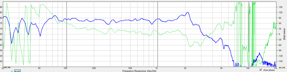
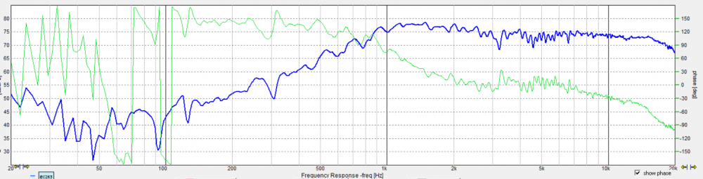
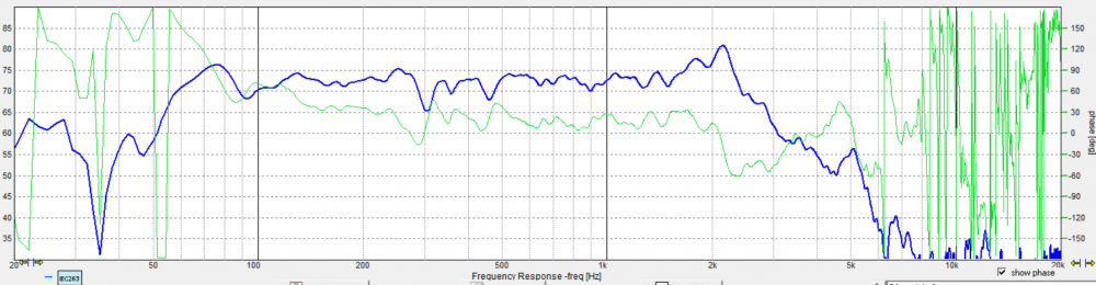
Running in 1.5way mode with a 2.0mH between the coils, and a 0.7mH out front:
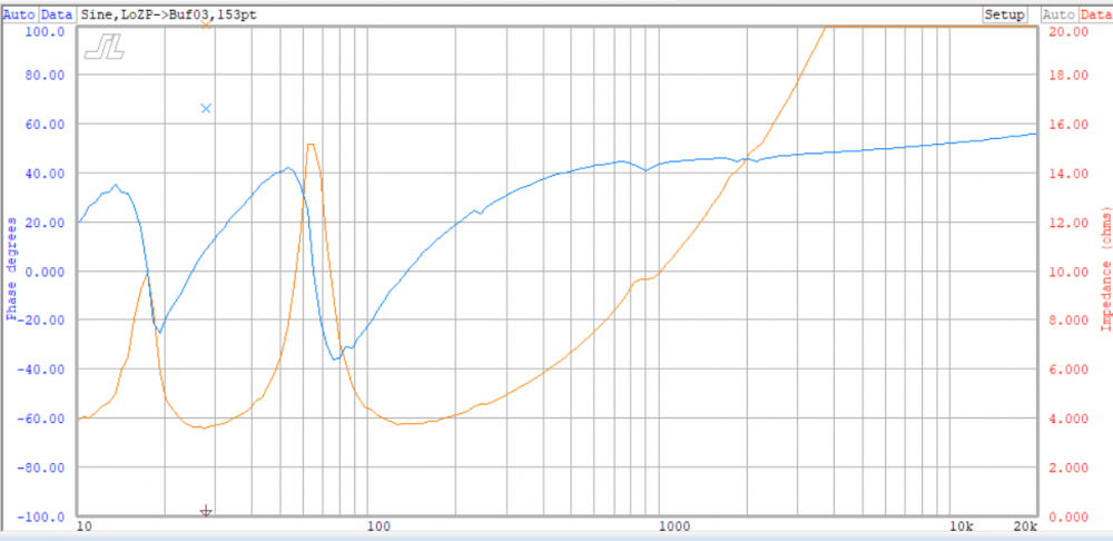
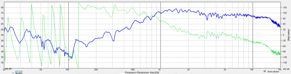
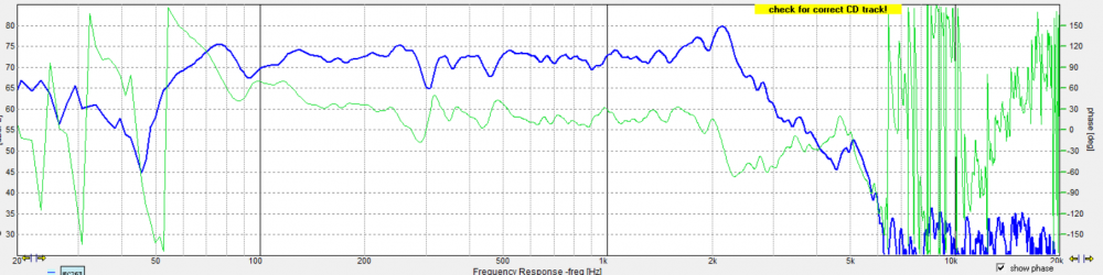
I apparently saved over the woofer on-axis with the notch with the woofer on tweeter-axis with the notch. Here that is:
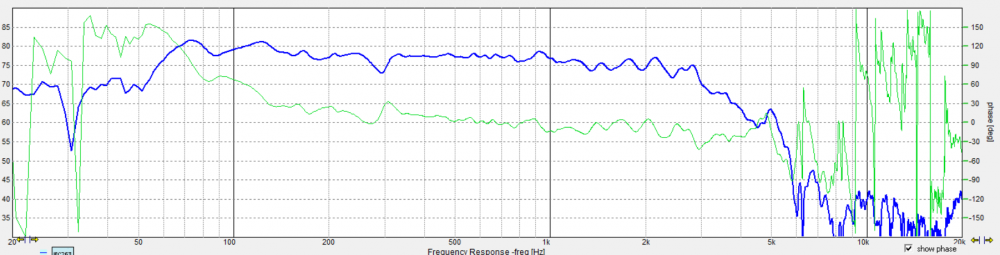
Circuit as pictured above:
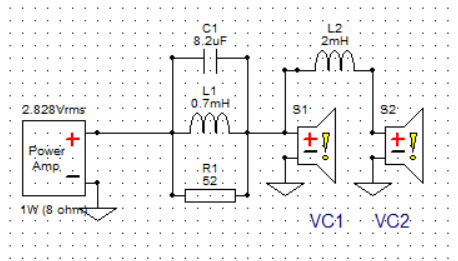
Thoughts...
The woofer has a really wide bandwidth for a 10". While I may have to tame the breakup further to make it unobjectionable, I feel the 50-75 ohm range is good to suppress to at least nominal output level. 80-100 suppressed to a considerable dip, but not right at the frequency in question as it was just above it. I was trying to see what it took to smooth it out alone.
The 0.5 coil really was fun dialing in. As I increased the value, the range around 200-300 dipped more prevalently. not enough and the response wasn't flat enough. I do have 1.2, 1.6, etc to try if I find later it doesn't sound right.
More to come...
InDIYana Event Website
Looks like I have to add more mass, tuning to 35+ currently....
InDIYana Event Website
Add more mass? To the woofer's cone?
Edit: maybe I missed it and you are using a passive radiator?
PR on the back...
InDIYana Event Website
which one / size ?
RSS265PR, the 10" Reference PR. Pretty sure it's in post #1.
InDIYana Event Website
Yup - thx
I’ve used those, very solidly built
1/2 meter?
I was just fooling around mainly. Half meter is just long enough to incorporate the baffle step influence due to baffle width. It is also easier to remove reflections at a closer measurement. It's not close enough to be nearfield, so no bass elevation is present. I was trying to be as accurate as possible to get the secondary coil blend without getting room influence in the measurement.
InDIYana Event Website
Thumbs up
That means, very good
Just found the Icore 2.0mH coils I have in my stash, and found a good place to mount and install them in the cabs.
In these cabs, if it's not near a magnet, it is near something that moves, or some steel. Since the PR is on the lower back, the drivers on the upper front, the corner handle in the top, and the input cup being large and between the handle and PR; the only good spots are on the inside of the lower front, or on the front half of the bottom panel. I chose the front, and made sure the PR bolt or mass do not come close to impacting the 2.0mH coil I placed there.
Now I should be able to get to the better measurements, all mounted and wired (except for the main xover stuff) out through the quad of rear binding posts.
I did add a mass washer to both PRs, I'll be verifying tunings there too.
Now the fun part starts....
InDIYana Event Website
Tunings look a lot better now. Measured at 27.5Hz and 30 Hz, when model was targeted at 32Hz. I'd say I'm there and ready for FR measurements in cab tomorrow with the cascaded coils in play.
InDIYana Event Website
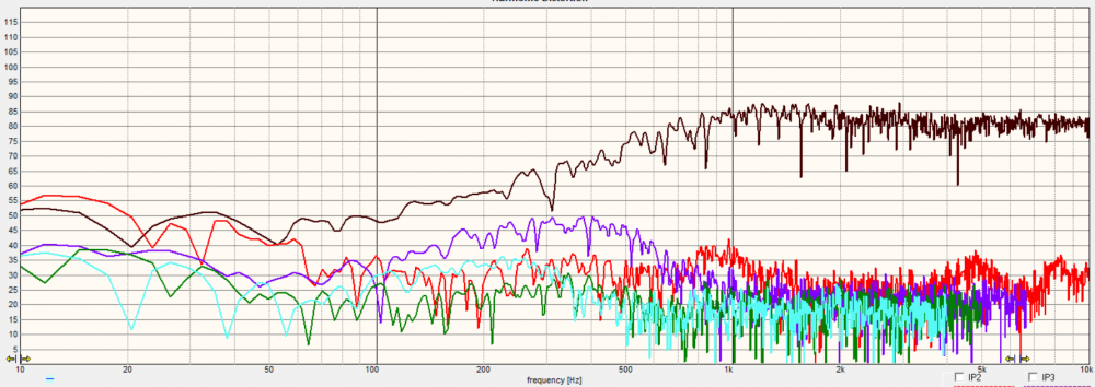
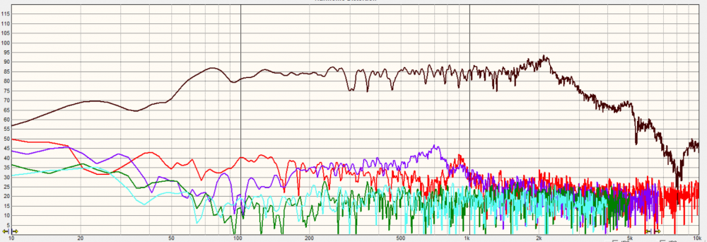
Data Dump time!!! I took H polars of 0/15/30/40, as 45 it might have fallen off due to imbalance. These are all taken at a reference of 1m on the tweeter axis, including the HD sweeps.
I must say I was rather pleased at the HD of these woofers, and find it actually cleaner in general than the SD215A-88 was in the Zingers. Clearly, the one RST28F has some problems below 500Hz with higher 3rd order. With the pending xover frequency, this should be mitigated in use.
I'm going to list these hopefully in order of H off-axis for Cab1, for the tweeter then woofer. I also have the HD for drivers in Cab2. I smartly used the drivers with sample number 1 in Cab1, and the number 2 drivers are in Cab2.
Cab1HD:
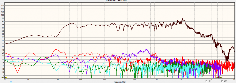
Cab2HD:
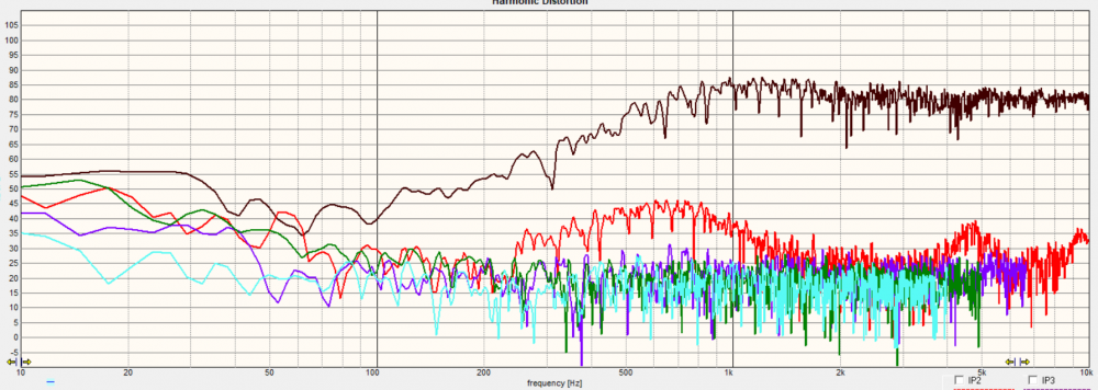
Cab1 Tweeter:
Cab1 Woofer:
InDIYana Event Website
Nice!
Sim1 done, LR4 at 1450Hz. I am surprised how wideband these drivers are being what they are. The xover is quite capacitance heavy, but not as many turns of copper compared to some others I've done. I opted for a full LCR across the tweeter Fs, as the resistor only method was in line to make the impedance more problematic than it already is. I also went for a full LCR across the woofer breakup. It reduces the level more than 20dB, but it is not that low from nominal output. I'll have to see how the directivity and breakup sound in this model to see whether further improvement is required. This is definitely a 4 ohm nominal system. I didn't bother fixing FR rolloff tails as I don't know how yet without Response Modeler. I don't think it suffers for it here. The phase alignment is really solid, and the FR variance is +/-2.5dB for the most part. Z-offset was measured to be -65mm.
InDIYana Event Website
Interesting no baffle step comp showing in your transfer functions.
That is because I already found that value empirically with the 2.0mH across to the second coil on the DVC woofers.
It has been accounted for.
InDIYana Event Website
Well, I tried to find the root of the high 3rd order in the low end of the modded B-Stock RST28F Sample 1.
Things I tried-
-swapped faces with the other tweeter, problem stayed with Sample 1.
-checked tension on screws, all were tight.
-used copper solid wire to feel gap for debris, nothing found.
-cut down wool plug atop the pole as it was about twice the size of the other tweeter wool plug.
-removed tape around chamber to check for leaks, nothing found.
I did find the gap is not quite concentric on the problematic sample, but the wire I used is larger than the former and coil thickness, so that shouldn't be the issue- but it might.
The measurement with a 20uF cap reduced the audibility considerably, so I'm hopeful the 3rd order electrical and Fs notch will ameliorate most of the problem. If it doesn't, it looks like I might be attempting to mod a good tweeter to match the first modded good unit. However, no RST tweeters until almost October. No trunkies, aluminum, textile, or replacement diaphragms.
InDIYana Event Website
I've got my two B-stocks from the grab-bags back whenever that MWAF was, I don't think I've ever taken them out of the box. If you want them, PM me you address.