I got them running yesterday. I think maybe I need to take the second PR tuning disc back off as while there is low extension, it seems to roll off too fast and a higher tuning should help that. The other option is more box volume, but that is not as easy to try. I think the tweeter might be a touch too sensitive in the balance area. Otherwise, I'm pretty impressed so far! There are better designs out there for sure. I feel like this is the most open sounding the RST has been for me, as typically they do sound a little stuffy or congested to me. I guess the cotton ball is doing its thing.
More later...
Nope, the tuning will remain the same. Did some listening this afternoon, and I'm not unhappy about the bass.
I tried shorting the notches across the resistors on both drivers, modeled to make sure the impedance would be fine and it is, and then changed the CR resistor on the woofer to a 4 ohm to adjust for the FR changes.
Audibly, this cut down on the woofer breakup bark to negligible and the tweeter is sounding a lot cleaner to me.
The bonus is the reverse null is now -5dB further down from where it was before.
13 parts for a 2.5 way doesn't seem too bad to me, and now the 2 resistors are not hanging off the edge or going through the coil like before.
No, as those are at the different extreme ends of the woofer response. The tweak to 4 ohms is around 700-800Hz effective, and the tuning disc affects mainly below 100Hz.
The low end being okay now could be chalked up to me being ill and plugged up a bit earlier this week, or even the stressful days I've had this week and BP being elevated with regards to either set of criteria. My daughter broke her arm in gym class taking a fall, and it has been a very stressful few days. It also could be that the woofer suspensions broke in a bit too.
I did a lot more listening last night after this last post, and the tweeter series resistor is now at 2 ohms. The tweeters were okay at 1.2 ohms when listening at lower output levels, especially to classical music. Dynamics were fine. When I turned them up a bit fatigue set in rather quickly. 2.2 ohms was dull sounding, and 1.8 ohms still felt a bit bright. If using a tube amp, I'd likely opt for a 1.5 or 1.8 ohm resistor due to the way the upper treble can sound, but for my Crown Drivecore, I prefer the 2.0 ohm value for a more level and even sound without being shouty or bright.
I have to say these surprise me in ways I didn't think they would. Vocals are surprisingly decent without being nasal, recessed, or stuffy. The bass is also quite tuneful and agile. Cello sounds great. There is a bit of bass emphasis around 80Hz, but it isn't objectionable and gives it some weight. The PR is definitely doing its job, however I'm amazed at how little the SD270 and RSS265PR actually move at higher levels. I would say I'm likely around 88dB sensitivity on these (soon to be verified), and it shows. These can get really loud really quick compared to my average 82-86dB designs.
More information to come...
Took them to Brad's place this afternoon. Different room yields a different perspective. I felt they were still a bit bright over there initially. We moved them closer to the front wall to about 2' like here at home, and the bass fleshed out better, but the tweeter still sounded a little bright. It wasn't a lot bright, but enough to be edgy. I've now added a half ohm in the negative tweeter lead for ease of addition, and will report more on this later. The reason I placed it there instead of adding to the 2 ohm resistor is because it would tilt the topend down more.
We took polar plots and measured output to 2.83V, which was louder than expected at 89dB before the half ohm was added. Up to the xover point it should still be 89dB. Yes, I know I said 2.2 ohms was dull prior, but it was a resistor type or brand I was unaccustomed to using and therefore an unknown entity. It may have been a resistor with higher inductance than the average sandcast.
I'll post the plots later, as they are on the laptop and this is on my phone.
What I'm saying is that a resistor on the amp side will not tilt the response, and on the driver side it will.
If I place a resistor on the negative line amp side, it is no different than an amp side positive line resistor.
Ease of addition and no tilt led the position.
Took them to Brad's place this afternoon. Different room yields a different perspective. I felt they were still a bit bright over there initially. We moved them closer to the front wall to about 2' like here at home, and the bass fleshed out better, but the tweeter still sounded a little bright. It wasn't a lot bright, but enough to be edgy. I've now added a half ohm in the negative tweeter lead for ease of addition, and will report more on this later. The reason I placed it there instead of adding to the 2 ohm resistor is because it would tilt the topend down more.
We took polar plots and measured output to 2.83V, which was louder than expected at 89dB before the half ohm was added. Up to the xover point it should still be 89dB. Yes, I know I said 2.2 ohms was dull prior, but it was a resistor type or brand I was unaccustomed to using and therefore an unknown quantity. It may have been a resistor with higher inductance than the average sandcast.
I'll post the plots later, as they are on the laptop and this is on my phone.
Amazing how a different room can change perspective. Thanks for sharing this type of detailed design info. I learn alot when an experienced builder, such as yourself, shares details of how they actually voice an xover. Good stuff. Look forward to hearing these next year.
@Wolf said:
What I'm saying is that a resistor on the amp side will not tilt the response, and on the driver side it will.
If I place a resistor on the negative line amp side, it is no different than an amp side positive line resistor.
Ease of addition and no tilt led the position.
Ok, that makes sense. The way you typed it was a bit corn fusing.👍🏻
More listening happened this afternoon. There is no longer any shout, and fatigue is greatly minimized. Even heavy metal isn't sonically offensive. I have yet to play Bonnie Raitt and Sarah Bareilles again, but Sarah McLachlan sounded really good. The half ohm will likely stay.
Okay, data dump again...
Obviously, the impedance will not dip below 4 ohms any longer because I've added enough resistance. I have not yet retaken the impedance measurement, but I felt this should be mentioned.
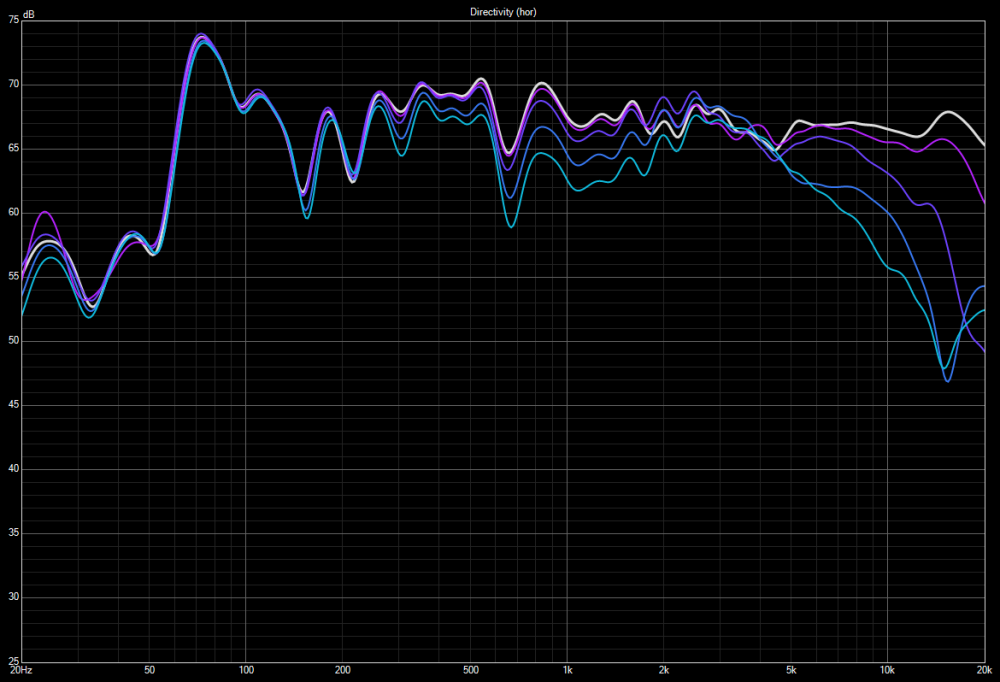
Since Thanh asked- These are the horizontal 0/15/30/45/60 plots BEFORE I added the 0.5 ohm resistance.
Cab1:
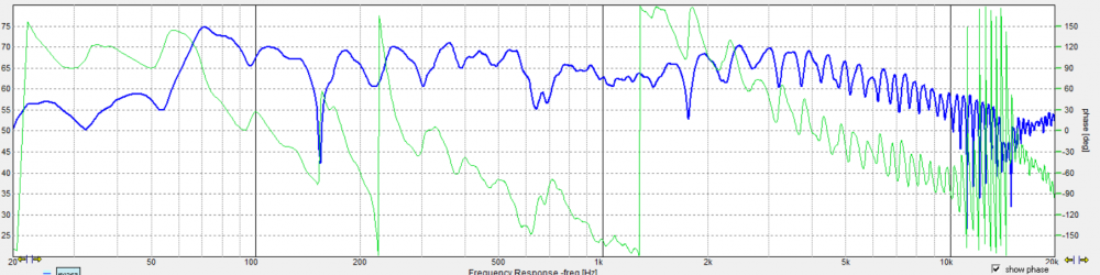
Cab2 at zero degrees to verify match to Cab1:
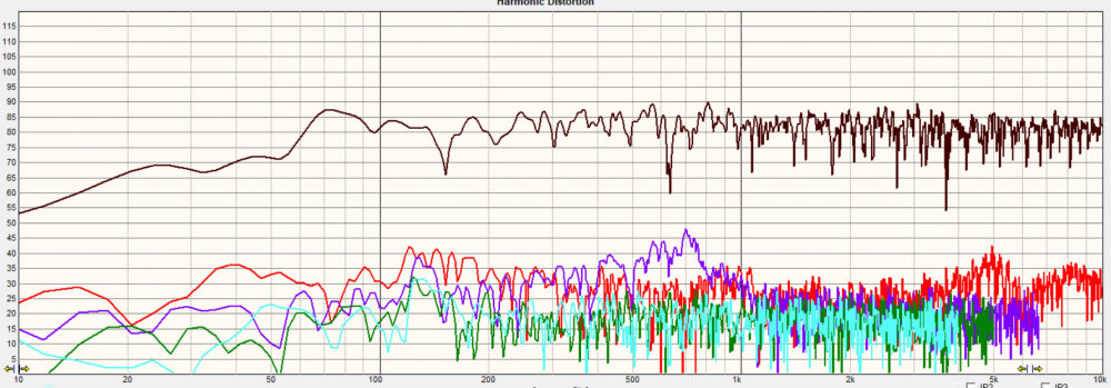
If referencing the previous graphs of the woofer and tweeter HD, you'll notice the 700Hz peaks of 3rd order in the woofer HD plots. As seen below with xover in place, these are still present. The higher 3rd order of the tweeter down closer to 300-500Hz is missing, so the xover cleaned up the tweeters' HD profile as intended.
This is the current circuit layout, just to show visually what I meant by resistor placement. The 0.5 ohm resistor can go at position R1 or R5, but not both. The effective attenuation is the same, and does not tilt the response like that of R4 does due to placement.
@Wolf said:
Okay, data dump again...
Obviously, the impedance will not dip below 4 ohms any longer because I've added enough resistance. I have not yet retaken the impedance measurement, but I felt this should be mentioned.
Since Thanh asked- These are the horizontal 0/15/30/45/60 plots BEFORE I added the 0.5 ohm resistance.
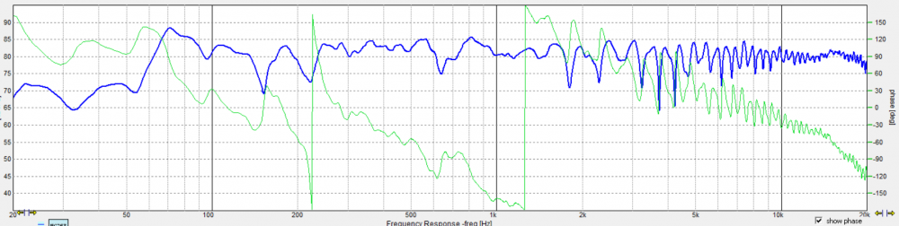
Have to say, for a 10 this (somewhat surprisingly) holds its off-axis crossover levels (0 thru 60 degrees) to the tweeter handover nicely. Interesting.
See, that's what I was getting at. I don't see how R1 doesn't effect the response the same as adding resistance to R4.
Resistance at R5 not effecting response I understand.
I see it almost like a voltage divider. The filter circuit is terminated/completed ahead of the resistor R1 and then that's connected to ground. I might be wrong though - my wife thinks I am most of the time!
I’m not familiar with Omnimic.
Under ~600Hz, floor bounce is causing peaks and valleys in the response, but What’s happening to give that grassy region in the FR, above 1KHz?
@Wolf said:
I was very surprised how well it did off axis. They don't make 10" like this very often.
Amazing. The directivity of a 1" dome tweeter, without waveguide, should be much wider than a big 10 inch woofer at 1.45kHz. But then I went back to page 1 again and looked at your H polars for this woofer. Looks like there is almost no roll off, all the way out to 5kHz at 45 degrees! What does the power response model for this speaker look like in Jeff's PCD spreadsheet?
I’m not familiar with Omnimic.
Under ~600Hz, floor bounce is causing peaks and valleys in the response, but What’s happening to give that grassy region in the FR, above 1KHz?
Does Omnimic auto-gate?
Yes. You have to check a box for "All", "Blended", or "Only to # of ms" to turn the gate on and off. When you open the program, the default is "Blended" and the gate is set at 5ms. If you check the "All" box, this turns off the gate, which, in turn, increases the amount of room reflection ripple at high frequencies.
Yes. You have to check a box for "All", "Blended", or "Only to # of ms" to turn the gate on and off. When you open the program, the default is "Blended" and the gate is set at 5ms. If you check the "All" box, this turns off the gate, which, in turn, increases the amount of room reflection ripple at high frequencies.
Well then if we use something like this we can choose an approximate gate:
I put in 1.2m to simulate the driver and mic at half the height of a typical 8’ ceiling, and measuring at 1m. That gives a gate of 4.5ms, which is a bit short. I can see now why the late Jeff Bagby advocated for measuring at twice the box width eg. 2 ft to get a longer gate and clearer midrange/treble response.
YMMV, which is why I like this quick tool- plug in and play hey?
H1/H2 is driver/mic distance from the ground respectively; d is measurement distance
I would have saved the FR and plotted them all on the same graph, but I forgot and only took snaps instead of saving the FRDs. Thanks for doing that, dB.
The ripples above 1k are the results of being in Brad's room. He has lower ceilings than I do. We measured at a meter distance because we were finding the 2.83V sensitivity first, and then took the polars.
The 0.5 ohm resistor is on the front or amp side of the ground node that terminates the tweeter shunt coil. This places it in the first circuit ring with the amp instead if in the second ring with the driver. If it was between the node and the driver, then it would act as R4 does.
Electrically, the way it's drawn, R1 is connected to the tweeter ground. There is no amp side/tweeter side. There's just ground. Everything in parallel with the tweeter is going through R1.
Comments
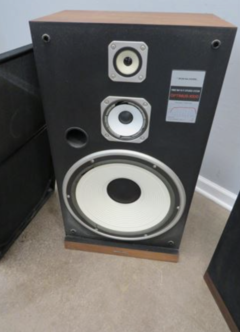
Just deciding on a tweeter. I want this design to be reproducible so that eliminates quite a bit of my inventory.
Alternatively I'll do a 3-way, probably with the MCM 4" aluminum woofer as the mid. Should be a reasonable cosmetic match.
This is kind of my favorite look for a speaker:
Anyways, as I get closer I'll start a thread and stop hijacking Ben's thread here.
No problem, JR-
I got them running yesterday. I think maybe I need to take the second PR tuning disc back off as while there is low extension, it seems to roll off too fast and a higher tuning should help that. The other option is more box volume, but that is not as easy to try. I think the tweeter might be a touch too sensitive in the balance area. Otherwise, I'm pretty impressed so far! There are better designs out there for sure. I feel like this is the most open sounding the RST has been for me, as typically they do sound a little stuffy or congested to me. I guess the cotton ball is doing its thing.
More later...
InDIYana Event Website
Nope, the tuning will remain the same. Did some listening this afternoon, and I'm not unhappy about the bass.
I tried shorting the notches across the resistors on both drivers, modeled to make sure the impedance would be fine and it is, and then changed the CR resistor on the woofer to a 4 ohm to adjust for the FR changes.
Audibly, this cut down on the woofer breakup bark to negligible and the tweeter is sounding a lot cleaner to me.
The bonus is the reverse null is now -5dB further down from where it was before.
13 parts for a 2.5 way doesn't seem too bad to me, and now the 2 resistors are not hanging off the edge or going through the coil like before.
I'm really digging these now! More to come...
InDIYana Event Website
Do you think the change to the woofer CR changed your impression of the rolloff issue you heard yesterday?
No, as those are at the different extreme ends of the woofer response. The tweak to 4 ohms is around 700-800Hz effective, and the tuning disc affects mainly below 100Hz.
The low end being okay now could be chalked up to me being ill and plugged up a bit earlier this week, or even the stressful days I've had this week and BP being elevated with regards to either set of criteria. My daughter broke her arm in gym class taking a fall, and it has been a very stressful few days. It also could be that the woofer suspensions broke in a bit too.
I did a lot more listening last night after this last post, and the tweeter series resistor is now at 2 ohms. The tweeters were okay at 1.2 ohms when listening at lower output levels, especially to classical music. Dynamics were fine. When I turned them up a bit fatigue set in rather quickly. 2.2 ohms was dull sounding, and 1.8 ohms still felt a bit bright. If using a tube amp, I'd likely opt for a 1.5 or 1.8 ohm resistor due to the way the upper treble can sound, but for my Crown Drivecore, I prefer the 2.0 ohm value for a more level and even sound without being shouty or bright.
I have to say these surprise me in ways I didn't think they would. Vocals are surprisingly decent without being nasal, recessed, or stuffy. The bass is also quite tuneful and agile. Cello sounds great. There is a bit of bass emphasis around 80Hz, but it isn't objectionable and gives it some weight. The PR is definitely doing its job, however I'm amazed at how little the SD270 and RSS265PR actually move at higher levels. I would say I'm likely around 88dB sensitivity on these (soon to be verified), and it shows. These can get really loud really quick compared to my average 82-86dB designs.
More information to come...
InDIYana Event Website
Hi Ben,
Is there any chance you are able to do a 45, or 60 degree off axis measurement?
I can, but I have not taken final FRs yet.
InDIYana Event Website
Took them to Brad's place this afternoon. Different room yields a different perspective. I felt they were still a bit bright over there initially. We moved them closer to the front wall to about 2' like here at home, and the bass fleshed out better, but the tweeter still sounded a little bright. It wasn't a lot bright, but enough to be edgy. I've now added a half ohm in the negative tweeter lead for ease of addition, and will report more on this later. The reason I placed it there instead of adding to the 2 ohm resistor is because it would tilt the topend down more.
We took polar plots and measured output to 2.83V, which was louder than expected at 89dB before the half ohm was added. Up to the xover point it should still be 89dB. Yes, I know I said 2.2 ohms was dull prior, but it was a resistor type or brand I was unaccustomed to using and therefore an unknown entity. It may have been a resistor with higher inductance than the average sandcast.
I'll post the plots later, as they are on the laptop and this is on my phone.
Edit, changed quantity to entity.
InDIYana Event Website
Your saying a resistor on the negative side doesn't tilt response like placing said resistor in the same position on the positive side?
What I'm saying is that a resistor on the amp side will not tilt the response, and on the driver side it will.
If I place a resistor on the negative line amp side, it is no different than an amp side positive line resistor.
Ease of addition and no tilt led the position.
InDIYana Event Website
aaa> @Wolf said:
Amazing how a different room can change perspective. Thanks for sharing this type of detailed design info. I learn alot when an experienced builder, such as yourself, shares details of how they actually voice an xover. Good stuff. Look forward to hearing these next year.
Ok, that makes sense. The way you typed it was a bit corn fusing.👍🏻
More listening happened this afternoon. There is no longer any shout, and fatigue is greatly minimized. Even heavy metal isn't sonically offensive. I have yet to play Bonnie Raitt and Sarah Bareilles again, but Sarah McLachlan sounded really good. The half ohm will likely stay.
InDIYana Event Website
Okay, data dump again...
Obviously, the impedance will not dip below 4 ohms any longer because I've added enough resistance. I have not yet retaken the impedance measurement, but I felt this should be mentioned.
Since Thanh asked- These are the horizontal 0/15/30/45/60 plots BEFORE I added the 0.5 ohm resistance.
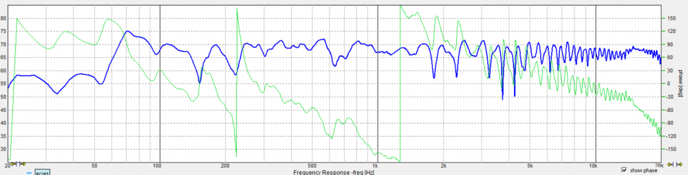
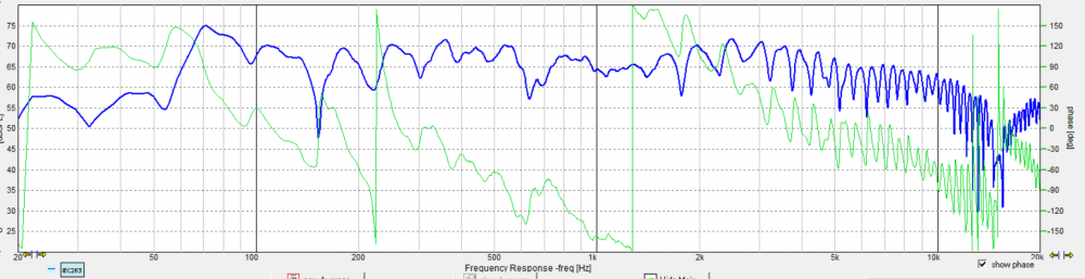
Cab1:
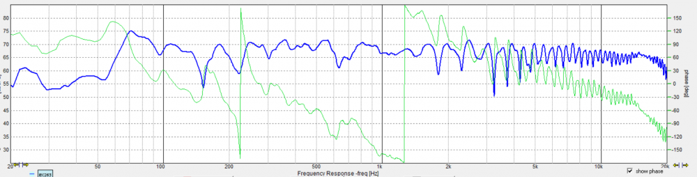
Cab2 at zero degrees to verify match to Cab1:
If referencing the previous graphs of the woofer and tweeter HD, you'll notice the 700Hz peaks of 3rd order in the woofer HD plots. As seen below with xover in place, these are still present. The higher 3rd order of the tweeter down closer to 300-500Hz is missing, so the xover cleaned up the tweeters' HD profile as intended.
Cab1 HD:
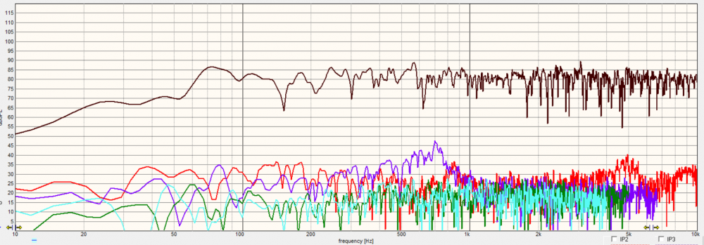
Cab2 HD:
InDIYana Event Website
This is the current circuit layout, just to show visually what I meant by resistor placement. The 0.5 ohm resistor can go at position R1 or R5, but not both. The effective attenuation is the same, and does not tilt the response like that of R4 does due to placement.
InDIYana Event Website
BTW-

This sounds AWESOME on these...
InDIYana Event Website
Have to say, for a 10 this (somewhat surprisingly) holds its off-axis crossover levels (0 thru 60 degrees) to the tweeter handover nicely. Interesting.
I was very surprised how well it did off axis. They don't make 10" like this very often.
InDIYana Event Website
See, that's what I was getting at. I don't see how R1 doesn't effect the response the same as adding resistance to R4.
Resistance at R5 not effecting response I understand.
I see it almost like a voltage divider. The filter circuit is terminated/completed ahead of the resistor R1 and then that's connected to ground. I might be wrong though - my wife thinks I am most of the time!
What does the inductor across the voice coils do?
Thanks Ben,
I’m not familiar with Omnimic.
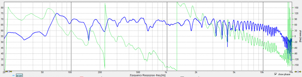
Under ~600Hz, floor bounce is causing peaks and valleys in the response, but What’s happening to give that grassy region in the FR, above 1KHz?
Does Omnimic auto-gate?
Amazing. The directivity of a 1" dome tweeter, without waveguide, should be much wider than a big 10 inch woofer at 1.45kHz. But then I went back to page 1 again and looked at your H polars for this woofer. Looks like there is almost no roll off, all the way out to 5kHz at 45 degrees! What does the power response model for this speaker look like in Jeff's PCD spreadsheet?
Nevermind, I see you explained that earlier on.
Yes. You have to check a box for "All", "Blended", or "Only to # of ms" to turn the gate on and off. When you open the program, the default is "Blended" and the gate is set at 5ms. If you check the "All" box, this turns off the gate, which, in turn, increases the amount of room reflection ripple at high frequencies.
Off-axis response set from above, traced, smoothed, and overlaid. Sorry, it looks fairly typical to me for this type of speaker.
Well then if we use something like this we can choose an approximate gate:
I put in 1.2m to simulate the driver and mic at half the height of a typical 8’ ceiling, and measuring at 1m. That gives a gate of 4.5ms, which is a bit short. I can see now why the late Jeff Bagby advocated for measuring at twice the box width eg. 2 ft to get a longer gate and clearer midrange/treble response.
YMMV, which is why I like this quick tool- plug in and play hey?
H1/H2 is driver/mic distance from the ground respectively; d is measurement distance
Reference:
https://mehlau.net/audio/floorbounce/
That would certainly clean up the fuzziness in midrange and treble and help clarify the anechoic response. On, AND, off-axis
I would have saved the FR and plotted them all on the same graph, but I forgot and only took snaps instead of saving the FRDs. Thanks for doing that, dB.
The ripples above 1k are the results of being in Brad's room. He has lower ceilings than I do. We measured at a meter distance because we were finding the 2.83V sensitivity first, and then took the polars.
The 0.5 ohm resistor is on the front or amp side of the ground node that terminates the tweeter shunt coil. This places it in the first circuit ring with the amp instead if in the second ring with the driver. If it was between the node and the driver, then it would act as R4 does.
InDIYana Event Website
Electrically, the way it's drawn, R1 is connected to the tweeter ground. There is no amp side/tweeter side. There's just ground. Everything in parallel with the tweeter is going through R1.