Okay, I received this pair from David this morning. Thanks, David!
Apparently, David's B-Stock F pair were slightly different. One had no grill or phase shield, while the other had a phase shield alone.
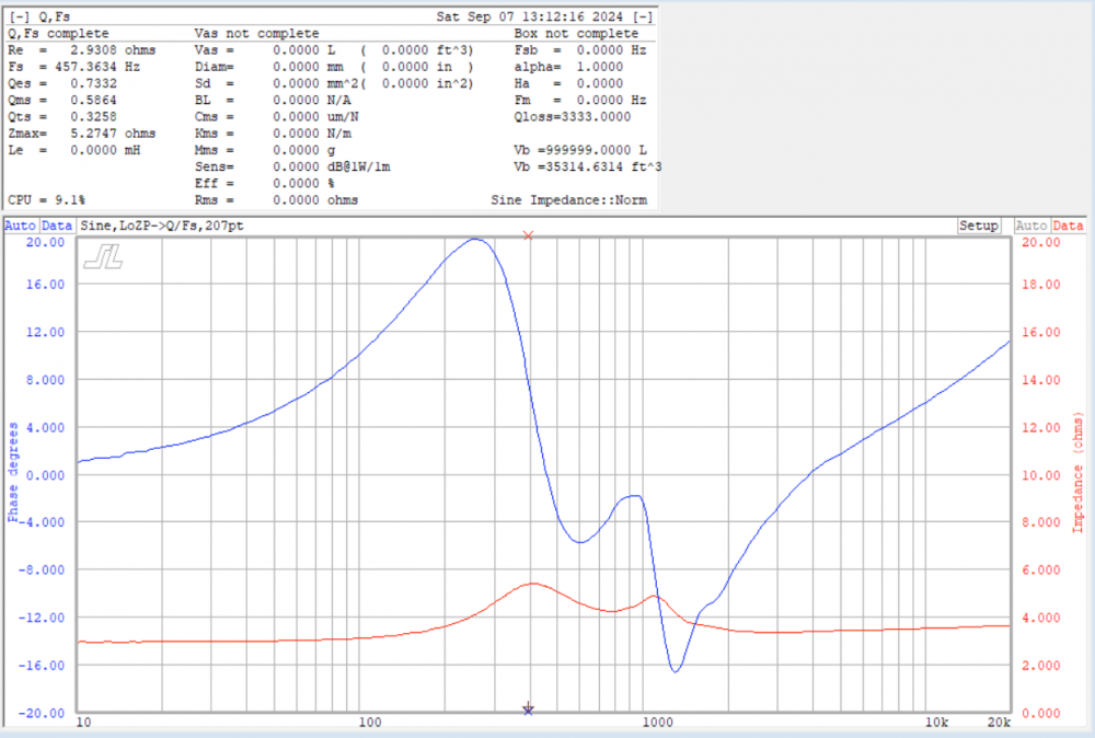
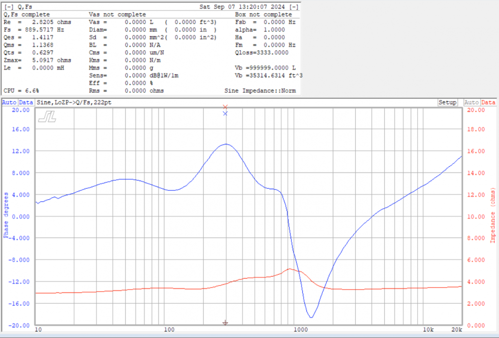
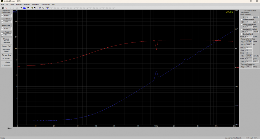
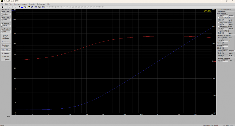
Data received from impedance was the usual garbage of these B-Stock units.
3:
4:
While I likely COULD improve the impedance and low level T/S specs of these doing what I did before on my pair, my initial endeavors here were to see if either motor could possibly be better than the one in the lesser of my previous 2 units.
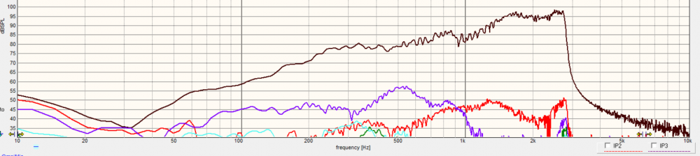
Before I set to doing HD sweeps, I removed the faces and verified that #3 had a disc-shaped wool pole cap, like the unit I was hoping to better or improve. I cut it down to a dome-shaped cap carefully with a pair of scissors in the case it would rub the dome inside under operation just like I did my previous unit. #4 had a dome shaped cap like that of my better unit. Unfortunately, while the HD3 is lower in the stopband, it was also higher in the operating bandwidth for #3, and #4 had a SERIOUS buzzing going on. It turns out that the replacement diaphragms are all fairly consistent, and it did not matter which dome was in which motor with the results being the same.
3:
4: (After I heard the buzz, I quit the measurement, but I likely should have let it do another sweep to stabilize.)
At the very least, I got an extra pair of voice coils in the case that I blow my altered pair. That is something I did not have before. At the next stage, #3 MAY be salvageable if I wish to try it. What I had prior seems to be the better path at this time.
I'm currently in process on building the networks as simulated. I had to wind 6 of the coils, and I'm doing layout at this time.
I've been told that I make xover construction like that of an art form. I try to not use jumpers if at all possible, but there are 2 jumpers on this one. It's a favorite puzzle of mine doing xover layout.
Low frequency low Q filters typically take larger parts to get the job done. With the 2 additonal notches I'm using, there are 2 more large caps to fix those issues. I couldn't bring myself to use NPEs. Since both drivers are Dayton Audio, I used all Dayton caps this time. I paralleled values to get the 20uF and 33uF.
Just in case anyone wants to know;
It took me 1 hour and 23 minutes to assemble and make connections on the second one, and maybe 10-15 minutes more to solder it up and connect leads. The first one takes a little longer due to creation of the layout, but then the pattern is easy to duplicate for the second one.
This is a 10" woofer 2-way project right? I'm fairly sure there is enough room somewhere in that enclosure for a more appropriate sized crossover board where the components aren't all jammed together touching each other, with some parts laying partially on top of the others, a resistor going through an air core inductor, and parts hanging over the edge of the board, etc? I seriously don't get it. Maybe if you had to sqeeze it through a 4" woofer hole, but otherwise why? Looks totally sloppy and amateurish to me. Lack of jumper wires are way over swamped by poor component placement IMHO.
I don't see how this is poor placement at all. The coils are all at right angles, and everything fits. There have been measurements shown and taken by others to see if the items within an air core are affected, and nothing was shown as far as passive speaker level to affect it detrimentally.
You say that there is supposedly ample room in these 25 ltr enclosures, and yet I described them earlier stating where it would have to go internally. Yes there is room, but it's not as large as you think, and this is about as big as I can fit inside without coming close to things in motion or adjacent to something metal or steel.
It's not a through the driver installation issue, but a tight spot for installation. As it sits, I will initially have it exterior on top while voicing.
Crossover design on your projects have been informative. However,
I’d be concerned of interaction of coils in that close of proximity, even at right angles.
I have found that when space is available it is best to use it.
I don't know all the constraints so I'm not here to criticize. There are a lot of great builders here and we could easily disolve into nit picking as all builds have a set of compromises.
I try to offer my honest yet polite opinion when asked and offer scientific or lived experiences when I feel it could be beneficial.
I feel very fortunate to have had very candid conversations with many of you in person about a broad range of topics and found you all have been very respectful; it's hard to maintain that same candor online.
@Wolf said:
I don't see how this is poor placement at all. The coils are all at right angles, and everything fits. There have been measurements shown and taken by others to see if the items within an air core are affected, and nothing was shown as far as passive speaker level to affect it detrimentally.
You say that there is supposedly ample room in these 25 ltr enclosures, and yet I described them earlier stating where it would have to go internally. Yes there is room, but it's not as large as you think, and this is about as big as I can fit inside without coming close to things in motion or adjacent to something metal or steel.
It's not a through the driver installation issue, but a tight spot for installation. As it sits, I will initially have it exterior on top while voicing.
He's made & defended his position already upthread.
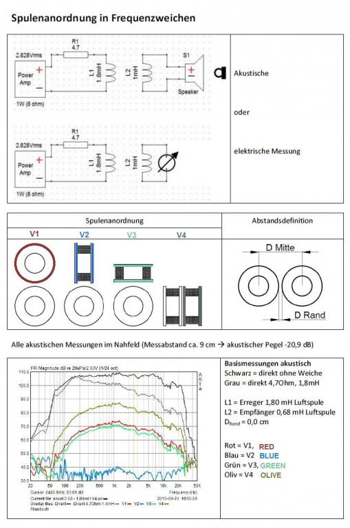
Javad is running a LOT of power to make those coils shake like that, and he is using laminate cored inductors for demonstration. These are more likely to couple than an air core will.
I've done this with this close of placement for years now, and have had no ill effects from either air or metal cores, and have measured little to no difference inductor values because of it. Place some steel nearby, and it will change drastically.
The most I've measured of value change by magnetic coupling has been between a .02mH and .05mH increase, and that has been for larger coils. In most cases, the lower value of .02 has happened, and that is usually less than the tolerance of the component value.
Just to be clear, when coils are touching, even if it's at 90 degrees there will be some crosstalk, but it will vary with frequency and coil value, generally be very low in level, and likely inaudible. Technically if the coils are absolutely in the right position the crosstalk will be almost zero, but nothing is perfect, and everything is a compromise. My two cents.
By the square of the distance. Javad's video is valid even if he took it to the extreme to prove the point. My argument is why buy drivers with low distortion if you're just going to add distortion to the final outcome because it's fun to build small crossovers when you really don't have to? The lack of jumper wires is an invalid argument. Proper mechanical and soldered connections add < 0.01 Ohms.
I did a simple test to have some level of measurements to add to the conversation, This was just a fun 20 min test.
Feeding a 1k 10v point-to-point square wave to a 2.4mH inductor, receiving through a matched 2.4mH coil playing through a sb10pgc21-4. I tested the crosstalk 3 ways:
Stacked one on top of the other (worst thing you could do): 86db
Figure "8" edge to edge on a flat plane:63db
Edge to edge twisted 90 degrees best case scenarieo for toutching (as Bed installed):53db
Ben, crosstalk is measured in db the mH should show almost no change at all. You would need to measure the change of the inductance with an impedance sweep:
just the coil:
Coil stacked on top of the other per the example:
@PWRRYD said:
Your 10 V peak to peak voltage into that driver at 1kHz is only about 3 Watts. Is this valid info?
Yes, this information is valid.
The voltage is the upper limit of my function generator, even at the upper limits my generator is fairly low distortion. To test at any higher output I would need to get a better function generator or use an amplifier (most amplifiers would not like that load and would be a variable in the test). It's safe to say the measurements will scale with voltage.
Testing the magnetic field with a gauss meter would be fun but I don't have a meter at home. Maybe I'll take a coil into work sometime.
Found what I was looking for. I'm familiar with crosstalk, and this set of measurements was all I needed to see to have the info required. Being this, as long as the values of the coils didn't change via inductive coupling (why I stated that earlier), then even tightly packed as I've done really shouldn't cause any major concerns.
I wasnt saying lack of jumpers was why or proof that this was okay. I CHOOSE to use this method as it makes it fun for me. It is just how I lay them out, and have been for quite some time.
This is what it took to make them small enough to install. This is a 25 ltr cabinet. That is less than a cubic foot. Said 25 ltrs has a 10" woofer and 10" PR vertically offset so that THEY fit internally as well. This is my homage to a 10" 2way of old using modern methods; think Dynaco, Advent, AR, etc, and have a bit more influence from Devore visually.
These cabinets were built with the premise of multiple builds within their confines, 3 pending total thus far, and all had to fit before I cut wood. Expect to see these again with yet a different set of drivers, and maybe some veneer...
I ordered a pair of the GRS white cone 10" because advertised response looks outstanding for a $20 paper cone driver. Not expecting a whole helluva lot out of it, but plan on doing a two way with it. Will be a wee bit bigger than 25L though.
Aw yeah, JBL style. Have had some DC25Ts collecting dust for years. Pair with a couple TC9FD18 or PC105s. Could be like a 3/4 scale L100 (probably sealed though).
Comments
Okay, I received this pair from David this morning. Thanks, David!
Apparently, David's B-Stock F pair were slightly different. One had no grill or phase shield, while the other had a phase shield alone.
Data received from impedance was the usual garbage of these B-Stock units.
3:
4:
While I likely COULD improve the impedance and low level T/S specs of these doing what I did before on my pair, my initial endeavors here were to see if either motor could possibly be better than the one in the lesser of my previous 2 units.
Before I set to doing HD sweeps, I removed the faces and verified that #3 had a disc-shaped wool pole cap, like the unit I was hoping to better or improve. I cut it down to a dome-shaped cap carefully with a pair of scissors in the case it would rub the dome inside under operation just like I did my previous unit. #4 had a dome shaped cap like that of my better unit. Unfortunately, while the HD3 is lower in the stopband, it was also higher in the operating bandwidth for #3, and #4 had a SERIOUS buzzing going on. It turns out that the replacement diaphragms are all fairly consistent, and it did not matter which dome was in which motor with the results being the same.
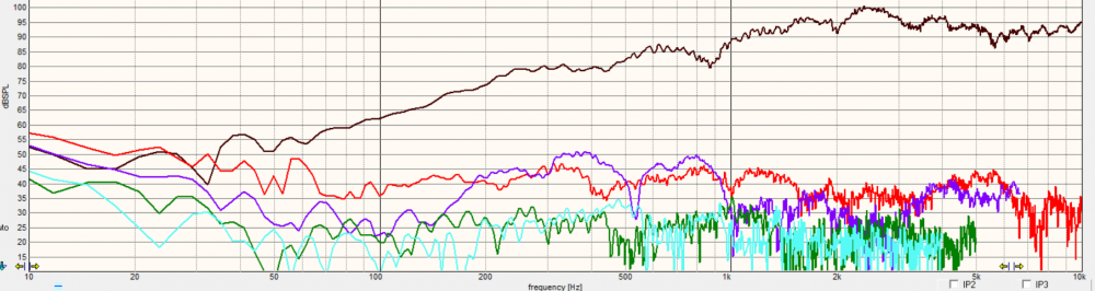
3:
4: (After I heard the buzz, I quit the measurement, but I likely should have let it do another sweep to stabilize.)
At the very least, I got an extra pair of voice coils in the case that I blow my altered pair. That is something I did not have before. At the next stage, #3 MAY be salvageable if I wish to try it. What I had prior seems to be the better path at this time.
I'm currently in process on building the networks as simulated. I had to wind 6 of the coils, and I'm doing layout at this time.
More to come!
InDIYana Event Website
Yeah, progress...
Needs solder and leads. The other is next now that this is constructed. 4x7 board, just beyond the edges in a few places....
InDIYana Event Website
I just LOVE your XO work, Ben!
Wish I could hear your efforts . . .
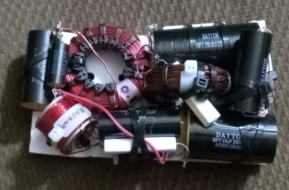
I've been told that I make xover construction like that of an art form. I try to not use jumpers if at all possible, but there are 2 jumpers on this one. It's a favorite puzzle of mine doing xover layout.
Low frequency low Q filters typically take larger parts to get the job done. With the 2 additonal notches I'm using, there are 2 more large caps to fix those issues. I couldn't bring myself to use NPEs. Since both drivers are Dayton Audio, I used all Dayton caps this time. I paralleled values to get the 20uF and 33uF.
InDIYana Event Website
The art of ruthless efficiency")
Both are soldered and have leads attached. Maybe tomorrow I can test them out.
InDIYana Event Website
Just in case anyone wants to know;
It took me 1 hour and 23 minutes to assemble and make connections on the second one, and maybe 10-15 minutes more to solder it up and connect leads. The first one takes a little longer due to creation of the layout, but then the pattern is easy to duplicate for the second one.
InDIYana Event Website
This is a 10" woofer 2-way project right? I'm fairly sure there is enough room somewhere in that enclosure for a more appropriate sized crossover board where the components aren't all jammed together touching each other, with some parts laying partially on top of the others, a resistor going through an air core inductor, and parts hanging over the edge of the board, etc? I seriously don't get it. Maybe if you had to sqeeze it through a 4" woofer hole, but otherwise why? Looks totally sloppy and amateurish to me. Lack of jumper wires are way over swamped by poor component placement IMHO.
I don't see how this is poor placement at all. The coils are all at right angles, and everything fits. There have been measurements shown and taken by others to see if the items within an air core are affected, and nothing was shown as far as passive speaker level to affect it detrimentally.
You say that there is supposedly ample room in these 25 ltr enclosures, and yet I described them earlier stating where it would have to go internally. Yes there is room, but it's not as large as you think, and this is about as big as I can fit inside without coming close to things in motion or adjacent to something metal or steel.
It's not a through the driver installation issue, but a tight spot for installation. As it sits, I will initially have it exterior on top while voicing.
InDIYana Event Website
You keep being you then.
At least we get to see his
Swing Drew swing!
We all have our individual methods and preferences...
Crossover design on your projects have been informative. However,
I’d be concerned of interaction of coils in that close of proximity, even at right angles.
I found Javad's video to be very informative:
I have found that when space is available it is best to use it.
I don't know all the constraints so I'm not here to criticize. There are a lot of great builders here and we could easily disolve into nit picking as all builds have a set of compromises.
I try to offer my honest yet polite opinion when asked and offer scientific or lived experiences when I feel it could be beneficial.
I feel very fortunate to have had very candid conversations with many of you in person about a broad range of topics and found you all have been very respectful; it's hard to maintain that same candor online.
He's made & defended his position already upthread.
Javad is running a LOT of power to make those coils shake like that, and he is using laminate cored inductors for demonstration. These are more likely to couple than an air core will.
I've done this with this close of placement for years now, and have had no ill effects from either air or metal cores, and have measured little to no difference inductor values because of it. Place some steel nearby, and it will change drastically.
InDIYana Event Website
The most I've measured of value change by magnetic coupling has been between a .02mH and .05mH increase, and that has been for larger coils. In most cases, the lower value of .02 has happened, and that is usually less than the tolerance of the component value.
InDIYana Event Website
Just to be clear, when coils are touching, even if it's at 90 degrees there will be some crosstalk, but it will vary with frequency and coil value, generally be very low in level, and likely inaudible. Technically if the coils are absolutely in the right position the crosstalk will be almost zero, but nothing is perfect, and everything is a compromise. My two cents.
If memory serves from school decades ago, the crosstalk falls off exponentially with distance.
By the square of the distance. Javad's video is valid even if he took it to the extreme to prove the point. My argument is why buy drivers with low distortion if you're just going to add distortion to the final outcome because it's fun to build small crossovers when you really don't have to? The lack of jumper wires is an invalid argument. Proper mechanical and soldered connections add < 0.01 Ohms.
I did a simple test to have some level of measurements to add to the conversation, This was just a fun 20 min test.
Feeding a 1k 10v point-to-point square wave to a 2.4mH inductor, receiving through a matched 2.4mH coil playing through a sb10pgc21-4. I tested the crosstalk 3 ways:
Stacked one on top of the other (worst thing you could do): 86db
Figure "8" edge to edge on a flat plane:63db
Edge to edge twisted 90 degrees best case scenarieo for toutching (as Bed installed):53db
Ben, crosstalk is measured in db the mH should show almost no change at all. You would need to measure the change of the inductance with an impedance sweep:
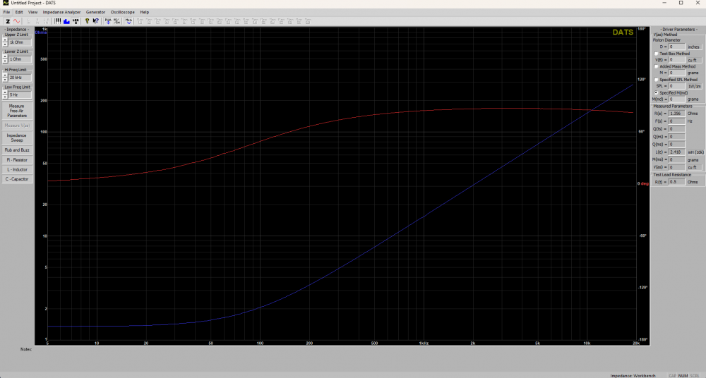
just the coil:
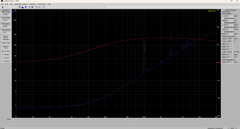
Coil stacked on top of the other per the example:
This is the sweep for best case scenario with the coils still touching:
This is best case scenarieo but with a 1 inch gap:
Your 10 V peak to peak voltage into that driver at 1kHz is only about 3 Watts. Is this valid info?
Yes, this information is valid.
The voltage is the upper limit of my function generator, even at the upper limits my generator is fairly low distortion. To test at any higher output I would need to get a better function generator or use an amplifier (most amplifiers would not like that load and would be a variable in the test). It's safe to say the measurements will scale with voltage.
Testing the magnetic field with a gauss meter would be fun but I don't have a meter at home. Maybe I'll take a coil into work sometime.
Found what I was looking for. I'm familiar with crosstalk, and this set of measurements was all I needed to see to have the info required. Being this, as long as the values of the coils didn't change via inductive coupling (why I stated that earlier), then even tightly packed as I've done really shouldn't cause any major concerns.
I wasnt saying lack of jumpers was why or proof that this was okay. I CHOOSE to use this method as it makes it fun for me. It is just how I lay them out, and have been for quite some time.
This is what it took to make them small enough to install. This is a 25 ltr cabinet. That is less than a cubic foot. Said 25 ltrs has a 10" woofer and 10" PR vertically offset so that THEY fit internally as well. This is my homage to a 10" 2way of old using modern methods; think Dynaco, Advent, AR, etc, and have a bit more influence from Devore visually.
These cabinets were built with the premise of multiple builds within their confines, 3 pending total thus far, and all had to fit before I cut wood. Expect to see these again with yet a different set of drivers, and maybe some veneer...
InDIYana Event Website
I ordered a pair of the GRS white cone 10" because advertised response looks outstanding for a $20 paper cone driver. Not expecting a whole helluva lot out of it, but plan on doing a two way with it. Will be a wee bit bigger than 25L though.
I've been pondering a budget 3-way with those same GRS woofers. I'll be watching to see what you think of them.
Aw yeah, JBL style. Have had some DC25Ts collecting dust for years. Pair with a couple TC9FD18 or PC105s. Could be like a 3/4 scale L100 (probably sealed though).
Then could go all out and make foam grills
https://www.foambymail.com/product/acoustical-1-pyramid-foam.html
They have various colors... Not that i've looked into this before or anything.