I do not see your reasoning. It is not connected between the node and the tweeter. It is connected to the negative input from the binding post and the node. This is AC, as it moves both ways. Your explanation explains neither thought process for me. If I'm wrong, please correct me, but I do not see how I am in this case. The tweeter and its conjugates are not terminated in the same way.
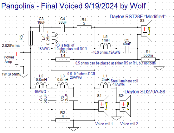
I couldn't leave well enough alone. It looks as though the first cap on the tweeter is the adjustable value that I need to look into changing for better directivity to take down the off axis bunching amplitude and approximates more what made the Zingers what they were. There are just times when they seem to get barky or harsh or sound a bit off without really needing to be.
Since I built the xover with an 18 and 2.0 in parallel, the first step is to just snip out the 2.0uF and see how it sounds. The phase alignment is still quite good even down to 15uF on that first value.
Hopefully, this will lead them in a positive direction.
Okay, that is done, and I can already tell the area of issue is definitely improved. I feel that going further will make them sound pretty dark in the mids, but this is already more preferable to the before.
@Wolf said:
I do not see your reasoning. It is not connected between the node and the tweeter. It is connected to the negative input from the binding post and the node. This is AC, as it moves both ways. Your explanation explains neither thought process for me. If I'm wrong, please correct me, but I do not see how I am in this case. The tweeter and its conjugates are not terminated in the same way.
Yeah, I don't know any other way of explaining it. To me as an electrical schematic, all of the parallel legs and tweeter go through R1.
Do you have any sims of the tweeter circuit without R1, with the .5ohm R1, and just adding the .5ohm to R4?
I can't seem to get my mind to see R1 resistance as the same as adding it to R5. To me it looks like whatever R4 does to the response, R1 would have too, because electrically it's connected directly to the tweeter, as R4 is.
Adding resistance at R1 or R5 is electrically the same. Think of all of the other high pass components and the tweeter as a black box (C3, C4, C5, L4, L5, R3, R4, and S3). The amp, R1, R5, and this "black box" are all in series with each other. Doesn't matter if you have the resistance added at the R1 position OR the R5 position. It is electrically equivalent.
Okay, I think I have these licked, measurements will come this weekend at some point.
I increased R3 and R1 to about 2 ohms total and 1.0 ohm for R1. What this does is gradually lean in the tweeter response like I did in the Zingers. They sound a LOT more balanced for it too. No shout in female vocals like Bonnie Raitt and Sara Bareilles. I'm sure the power response is also much improved because of this as well.
Gotta kick them with some rock and classical, but the vocal ranges are how I like them now.
We'll call this Final Revision C.
Meshuggah, Dream Theater, Diana Krall, Imagine Dragons, Eric Clapton, Chris Jones, and Demi Lovato all sound really good and clean. I am now fully happy with these!
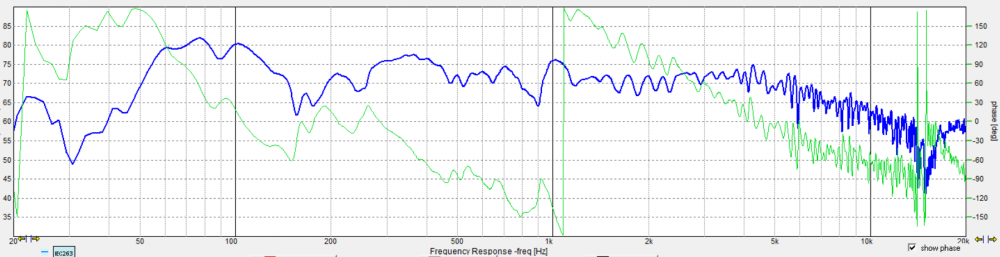
Okay, final FR data dump....
All axes, 0/10/15/30/45/60:
0
10
15
30
45
60
Obviously, the dip at 150Hz is the floor bounce. I feel these are a better example of good directivity than the previous assembled xover schematic. They sound a lot better too. Are they great or fantastic directivity/DI? maybe not, but they do sound very good like this. They will remain like this for the foreseeable future.
I need to get a final impedance sweep, but I'm having too much fun listening at the moment...
The design looks pretty solid. I have one simple suggestion (has nothing to do with your design) but I usually smooth distortion measurements to 1/12th just to make them easier to see when using OmniMic.
I haven't had any time to fiddle with my 8" 2-way for a few weeks, but this is helping the motivation.
How are you measuring your responses? I'm sorry if this was mentioned already, but it looks like there is a lot of room interaction. Have you tried/is it possible to measure outdoors? Even a 6-8 foot ladder ~20 feet or more from boundaries would work really well. And in-room measurements of distortion I've found are almost useless. I measured my 3-way towers outside and had the ~75 dB down third order I bragged about. I measured in-house (empty and no other people here, AC off) and it was ~45 dB down.
I've never done outdoor measurements, but I have thought about trying it with these. They are kind of awkward to handle, and I'd have to figure out how. There is a lot of traffic and a distant highway noise here though.
I usually have them half between ceiling and floor, further from walls, and at non parallel directions. My floor bounce at 150 is just a constant blemish.
I don't normally smooth because I want to see all the warts. Thanks for the suggestions.
Just so you all know, I felt they were bright in an 800-1k kinda way Saturday, and plan on seeing if a slight reduction here fixes what I was hearing. I don't feel they are bright or peaking off axis in the lower tweeter end. Other than this, I don't feel these are all that bad at all. Several were surprised at the midrange from a 10" driver.
Okay, I am TOTALLY HAPPY now. They are now even better than I imagined they could be. Turns out I was right to think they were bright in that 800-1k range. I increased the woofer LP cap by 10uF to 60uF, and further paralleled a Russian PIO 0.47uF across it as it seemed to be a favorable result. +8.2uF wasn't enough to bring it down, and +12uF was too much and made it dull.
Did some torture testing after this adjustment, and I did not have any complaints until I was measuring over 100dB at about 9 feet. The drivers were not complaining, nor were they fatiguing. The impact of the Firebird Suite by Stravinsky on Reference Recordings was just AWESOME!!! And- they really weren't even moving that much.
I'm very glad I revisited these after last weekend. I feel I have now achieved the best from these drivers in this configuration, and they really are better than expected.
Now it's on to finish the cabinets so they look a lot better....
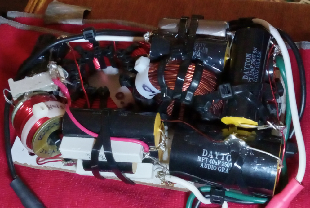
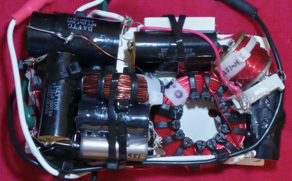
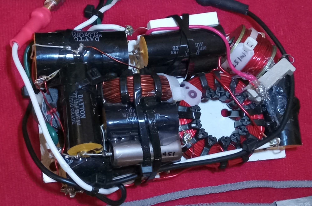
Final physical layout, need 3 images to see it all. Of note; yes, there seem to be excessive solder blobs in some places. This is because most of the caps were used or second hand. A lot of them had solder and bits of trimmed away joints along for the ride. Thusly, they remain to an extent. I'll likely be doing an outboard box just because this time, as i just want to! The MonkeyBox mule cabs will get a paralleled Neutrik input jack so I can use various connectivity on these or in the future. That was part of the plan anyway.
Ya, that's one congested looking xover. I counted 13 zip ties on that one inductor. Looks like the other inductor has quite a few as well. What's that about? EDIT: Not 13, but 15 including two more I missed on the first count.
I wound those myself, Bill, so I had to bind the windings. They are bobbinless coils, so the form/jig starts with 4 ties. I add until I see fit with T&B steel barbed ties. There are 4 on the board, one in the cabinet off-board for the 0.5 sector. 3 on each board I wound myself.
You need to make a youtube video showing how you wind these. I'd like to see all the sequential steps. Or is there a thread somewhere showing the entire process?
I'm pretty sure I have it posted on multiple forums. I have not however posted the updated jigs I did a year ago.
This is the 2" jig pictured here. I have a 1.5" and 2" jig, and 2 stackable hubs for each one if I want bobbinless coils. The recessed rings in the plates allow for clamping PVC or ABS rings into the jig to use as formers. Litz wire is very flexible unlike solid core, so a former is preferred to keep them more stable physically. The plates are 3/8" Lexan, which is much stronger than the 0.23" acrylic I used the first go around. These are smaller in diameter than the previous 6" plates at 4.75" diameter.
I bring in the annealed polyurethane coated copper wire through between the plates of the assembled jig, and hook it through one slit and sometimes around the wingnut to secure the one end of the wire. The end has to be scraped of enamel to get a reading during the process. Then I let the spool on the floor roll tight towards my couch between my feet, or hold the wire with one of the 2 hands operating the winding of the jig and allow the source spool to unwind loosely. The important point is that the wire stay taught as it winds around the center hub. I use the binder clip to take a break or pause the process, and then scratch enamel off beyond the jig to take a reading of inductance. A small amount missing will be covered by the next layer, and therefore isn't usually a problem. I use a basic LC meter, nothing fancy.
When the value is as wanted, employ binder clamp and cut wire with good length outside of the spool. 4-5" should be plenty. Insert zip ties into 4 notches, fold through jig, and zip hand tight. I use a zip-tie gun from Paladin Tools to make them as tight as possible. Don't cut the excess yet as they may need further tightening after the jig is disassembled. Remove binder clip and bend cut length back to not lose tension around ties. Undo wingnut and disassemble by removing the plates and through bolt. Tighten ties and cut excess now. The center hub if choosing bobbinless will be held very tight and need removed. Using a thin screwdriver set through the hole and a mallet of sorts makes tapping the hub out pretty easy by hand. If you chose to use a ring former, the ring doesn't need removed, and you have your coil as it sits.
My preference is for at least 8 even spaced zip ties per coil, and dunking in polyurethane is recommended for binding of the windings. If you don't dunk them, zip them to oblivion to keep them solid. If "rat's nest coils" (Mark Sayer's term) can be bound by tape alone and be acceptable, this should suffice.
Thanks for the detailed procedures. Now I can see clearly how you go about this. I've seen many of your posts and pictures showing similar jigs in the past, but I never fully understood how it was held together during the winding process or how the zip ties were finally added at the end. Good stuff.
For the two small 0.09mH coils that I made for my InDIYana project, I tightly hand wound them in a similar fashion. Instead of using a binder clip, however, I tightly wrapped a single layer of masking tape between layers to hold it together as I went along. I stopped at 7 layers, which was very close to my target and measured the value by pushing an exacto blade into the enamel wire, which, in turn, was electrically connected to one of my DATS V2 allegator clips. If over, I unwound a couple turns. If under, I added a couple more turns. The 1/2" diameter by 1" nylon spacer hubs and 1/8" thick masonite plates stayed in place as a permanent part of my coil.
First couple spools I bought remnants from someone that was selling it for a great price. Reloaded the first and second times from Amazon seller Temco that appears to no longer sell it that way. I found a cheaper vendor last year this last time as prices have increased, and have even been happier than the others. They use a double coating process. Found it, BAE wire and insulation.
That said, Essex, Remington, etc all have good stuff.
I have a big roll of 16ga magnet wire I picked up a long time ago, can't remember where or what the price/ft was. Also have some old rolls of 18 and 20ga magnet wire from some old madisound air core inductors that I can unwind and repurpose. I made the .09mH units with 20ga wire. Not a big inventory, but enough to get by in a pinch. American Science and Surplus in Milwaukee (they also have a Chicago location) also sells magnet wire per foot from big rolls, but it is kind of pricy. This is where I can go to get wire to rewind an open RF coil in a radio, if I want to pay the price. But to make a speaker coil, I would be much better off ordering a pre-made one.
I bought magnet wire from a local motor rewind place here in town many years ago. I just told them how many pounds I wanted and they wound it on a spool for me.
Comments
I do not see your reasoning. It is not connected between the node and the tweeter. It is connected to the negative input from the binding post and the node. This is AC, as it moves both ways. Your explanation explains neither thought process for me. If I'm wrong, please correct me, but I do not see how I am in this case. The tweeter and its conjugates are not terminated in the same way.
InDIYana Event Website
I couldn't leave well enough alone. It looks as though the first cap on the tweeter is the adjustable value that I need to look into changing for better directivity to take down the off axis bunching amplitude and approximates more what made the Zingers what they were. There are just times when they seem to get barky or harsh or sound a bit off without really needing to be.
Since I built the xover with an 18 and 2.0 in parallel, the first step is to just snip out the 2.0uF and see how it sounds. The phase alignment is still quite good even down to 15uF on that first value.
Hopefully, this will lead them in a positive direction.
InDIYana Event Website
Okay, that is done, and I can already tell the area of issue is definitely improved. I feel that going further will make them sound pretty dark in the mids, but this is already more preferable to the before.
Always listening and searching until I'm happy...
InDIYana Event Website
Currently:
InDIYana Event Website
Now I'm messing with removing the 0.5 ohm resistor, which apparently only masked the problem before.
InDIYana Event Website
Yeah, I don't know any other way of explaining it. To me as an electrical schematic, all of the parallel legs and tweeter go through R1.
Do you have any sims of the tweeter circuit without R1, with the .5ohm R1, and just adding the .5ohm to R4?
I can't seem to get my mind to see R1 resistance as the same as adding it to R5. To me it looks like whatever R4 does to the response, R1 would have too, because electrically it's connected directly to the tweeter, as R4 is.
Adding resistance at R1 or R5 is electrically the same. Think of all of the other high pass components and the tweeter as a black box (C3, C4, C5, L4, L5, R3, R4, and S3). The amp, R1, R5, and this "black box" are all in series with each other. Doesn't matter if you have the resistance added at the R1 position OR the R5 position. It is electrically equivalent.
But they're not. R5 isn't connected directly to the tweeter. R4 is. R1 is.
Not trying to be argumentative, trying to understand.
Amp(+) R5 (Everything between node 1 and node 2) R1 Amp(-)
That's your series loop. Nothing between Nodes 1 and 2 changes.
Okay, I think I have these licked, measurements will come this weekend at some point.
I increased R3 and R1 to about 2 ohms total and 1.0 ohm for R1. What this does is gradually lean in the tweeter response like I did in the Zingers. They sound a LOT more balanced for it too. No shout in female vocals like Bonnie Raitt and Sara Bareilles. I'm sure the power response is also much improved because of this as well.
Gotta kick them with some rock and classical, but the vocal ranges are how I like them now.
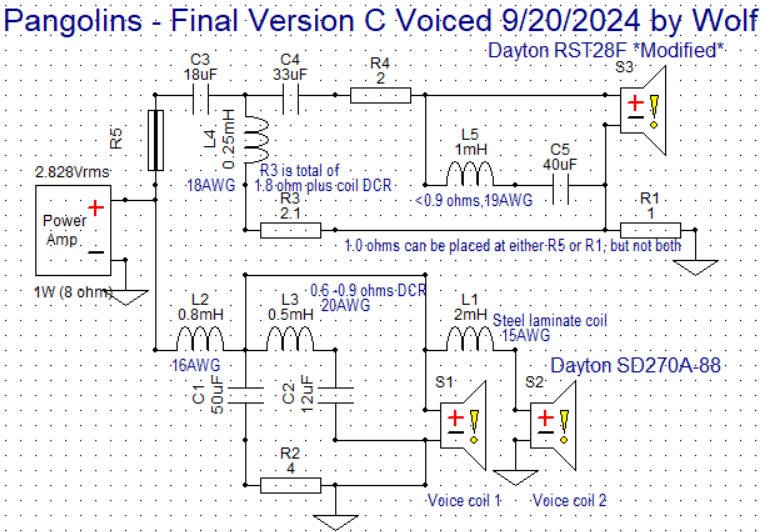
We'll call this Final Revision C.
InDIYana Event Website
Meshuggah, Dream Theater, Diana Krall, Imagine Dragons, Eric Clapton, Chris Jones, and Demi Lovato all sound really good and clean. I am now fully happy with these!
InDIYana Event Website
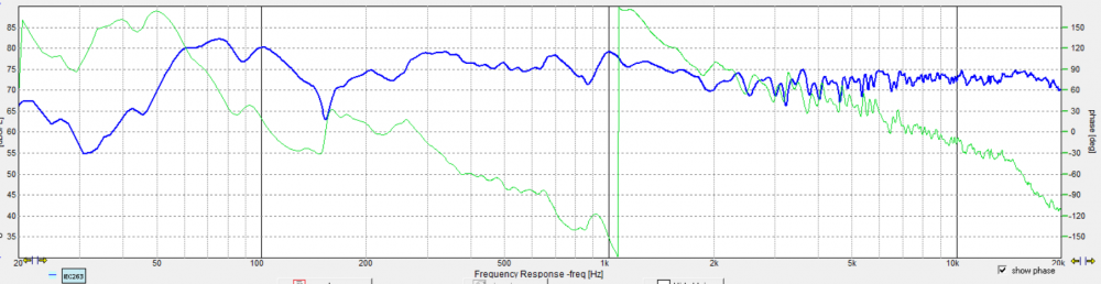
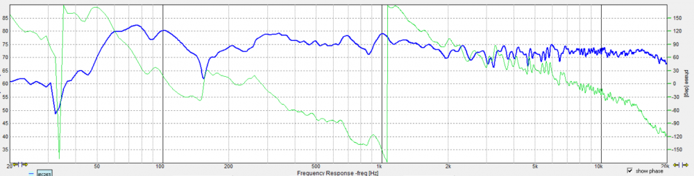
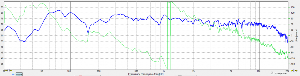
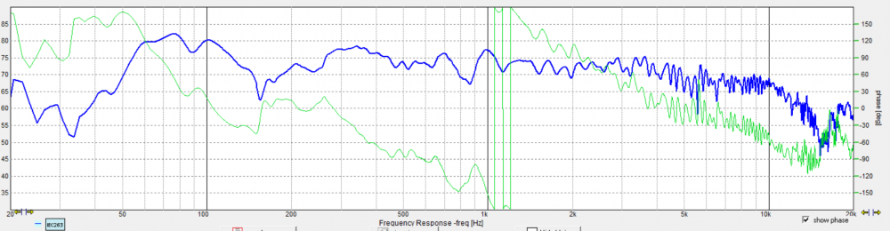
Okay, final FR data dump....
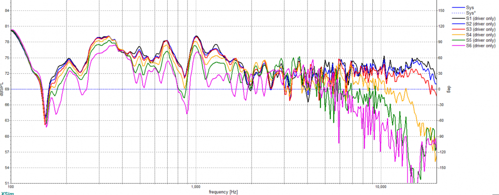
All axes, 0/10/15/30/45/60:
0
10
15
30
45
60
Obviously, the dip at 150Hz is the floor bounce. I feel these are a better example of good directivity than the previous assembled xover schematic. They sound a lot better too. Are they great or fantastic directivity/DI? maybe not, but they do sound very good like this. They will remain like this for the foreseeable future.
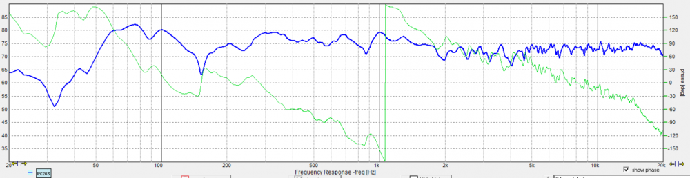
I need to get a final impedance sweep, but I'm having too much fun listening at the moment...
InDIYana Event Website
Hey Wolf,
The design looks pretty solid. I have one simple suggestion (has nothing to do with your design) but I usually smooth distortion measurements to 1/12th just to make them easier to see when using OmniMic.
I haven't had any time to fiddle with my 8" 2-way for a few weeks, but this is helping the motivation.
How are you measuring your responses? I'm sorry if this was mentioned already, but it looks like there is a lot of room interaction. Have you tried/is it possible to measure outdoors? Even a 6-8 foot ladder ~20 feet or more from boundaries would work really well. And in-room measurements of distortion I've found are almost useless. I measured my 3-way towers outside and had the ~75 dB down third order I bragged about. I measured in-house (empty and no other people here, AC off) and it was ~45 dB down.
I've never done outdoor measurements, but I have thought about trying it with these. They are kind of awkward to handle, and I'd have to figure out how. There is a lot of traffic and a distant highway noise here though.
I usually have them half between ceiling and floor, further from walls, and at non parallel directions. My floor bounce at 150 is just a constant blemish.
I don't normally smooth because I want to see all the warts. Thanks for the suggestions.
InDIYana Event Website
I did outdoor measurements for a while until my mic did a face plant in the ground like a jart.
It was a strange sensation hearing real midrange come out of a 10" subwoofer.
Just so you all know, I felt they were bright in an 800-1k kinda way Saturday, and plan on seeing if a slight reduction here fixes what I was hearing. I don't feel they are bright or peaking off axis in the lower tweeter end. Other than this, I don't feel these are all that bad at all. Several were surprised at the midrange from a 10" driver.
InDIYana Event Website
Okay, I am TOTALLY HAPPY now. They are now even better than I imagined they could be. Turns out I was right to think they were bright in that 800-1k range. I increased the woofer LP cap by 10uF to 60uF, and further paralleled a Russian PIO 0.47uF across it as it seemed to be a favorable result. +8.2uF wasn't enough to bring it down, and +12uF was too much and made it dull.
Did some torture testing after this adjustment, and I did not have any complaints until I was measuring over 100dB at about 9 feet. The drivers were not complaining, nor were they fatiguing. The impact of the Firebird Suite by Stravinsky on Reference Recordings was just AWESOME!!! And- they really weren't even moving that much.
I'm very glad I revisited these after last weekend. I feel I have now achieved the best from these drivers in this configuration, and they really are better than expected.
Now it's on to finish the cabinets so they look a lot better....
InDIYana Event Website
Final physical layout, need 3 images to see it all. Of note; yes, there seem to be excessive solder blobs in some places. This is because most of the caps were used or second hand. A lot of them had solder and bits of trimmed away joints along for the ride. Thusly, they remain to an extent. I'll likely be doing an outboard box just because this time, as i just want to! The MonkeyBox mule cabs will get a paralleled Neutrik input jack so I can use various connectivity on these or in the future. That was part of the plan anyway.
InDIYana Event Website
Ya, that's one congested looking xover. I counted 13 zip ties on that one inductor. Looks like the other inductor has quite a few as well. What's that about? EDIT: Not 13, but 15 including two more I missed on the first count.
I wound those myself, Bill, so I had to bind the windings. They are bobbinless coils, so the form/jig starts with 4 ties. I add until I see fit with T&B steel barbed ties. There are 4 on the board, one in the cabinet off-board for the 0.5 sector. 3 on each board I wound myself.
InDIYana Event Website
You need to make a youtube video showing how you wind these. I'd like to see all the sequential steps. Or is there a thread somewhere showing the entire process?
I'm pretty sure I have it posted on multiple forums. I have not however posted the updated jigs I did a year ago.
This is the 2" jig pictured here. I have a 1.5" and 2" jig, and 2 stackable hubs for each one if I want bobbinless coils. The recessed rings in the plates allow for clamping PVC or ABS rings into the jig to use as formers. Litz wire is very flexible unlike solid core, so a former is preferred to keep them more stable physically. The plates are 3/8" Lexan, which is much stronger than the 0.23" acrylic I used the first go around. These are smaller in diameter than the previous 6" plates at 4.75" diameter.
I bring in the annealed polyurethane coated copper wire through between the plates of the assembled jig, and hook it through one slit and sometimes around the wingnut to secure the one end of the wire. The end has to be scraped of enamel to get a reading during the process. Then I let the spool on the floor roll tight towards my couch between my feet, or hold the wire with one of the 2 hands operating the winding of the jig and allow the source spool to unwind loosely. The important point is that the wire stay taught as it winds around the center hub. I use the binder clip to take a break or pause the process, and then scratch enamel off beyond the jig to take a reading of inductance. A small amount missing will be covered by the next layer, and therefore isn't usually a problem. I use a basic LC meter, nothing fancy.
When the value is as wanted, employ binder clamp and cut wire with good length outside of the spool. 4-5" should be plenty. Insert zip ties into 4 notches, fold through jig, and zip hand tight. I use a zip-tie gun from Paladin Tools to make them as tight as possible. Don't cut the excess yet as they may need further tightening after the jig is disassembled. Remove binder clip and bend cut length back to not lose tension around ties. Undo wingnut and disassemble by removing the plates and through bolt. Tighten ties and cut excess now. The center hub if choosing bobbinless will be held very tight and need removed. Using a thin screwdriver set through the hole and a mallet of sorts makes tapping the hub out pretty easy by hand. If you chose to use a ring former, the ring doesn't need removed, and you have your coil as it sits.
My preference is for at least 8 even spaced zip ties per coil, and dunking in polyurethane is recommended for binding of the windings. If you don't dunk them, zip them to oblivion to keep them solid. If "rat's nest coils" (Mark Sayer's term) can be bound by tape alone and be acceptable, this should suffice.
InDIYana Event Website
Thanks for the detailed procedures. Now I can see clearly how you go about this. I've seen many of your posts and pictures showing similar jigs in the past, but I never fully understood how it was held together during the winding process or how the zip ties were finally added at the end. Good stuff.
For the two small 0.09mH coils that I made for my InDIYana project, I tightly hand wound them in a similar fashion. Instead of using a binder clip, however, I tightly wrapped a single layer of masking tape between layers to hold it together as I went along. I stopped at 7 layers, which was very close to my target and measured the value by pushing an exacto blade into the enamel wire, which, in turn, was electrically connected to one of my DATS V2 allegator clips. If over, I unwound a couple turns. If under, I added a couple more turns. The 1/2" diameter by 1" nylon spacer hubs and 1/8" thick masonite plates stayed in place as a permanent part of my coil.
Looks great - both of you. Where do you all get your wire?
First couple spools I bought remnants from someone that was selling it for a great price. Reloaded the first and second times from Amazon seller Temco that appears to no longer sell it that way. I found a cheaper vendor last year this last time as prices have increased, and have even been happier than the others. They use a double coating process. Found it, BAE wire and insulation.
That said, Essex, Remington, etc all have good stuff.
InDIYana Event Website
I have a big roll of 16ga magnet wire I picked up a long time ago, can't remember where or what the price/ft was. Also have some old rolls of 18 and 20ga magnet wire from some old madisound air core inductors that I can unwind and repurpose. I made the .09mH units with 20ga wire. Not a big inventory, but enough to get by in a pinch. American Science and Surplus in Milwaukee (they also have a Chicago location) also sells magnet wire per foot from big rolls, but it is kind of pricy. This is where I can go to get wire to rewind an open RF coil in a radio, if I want to pay the price. But to make a speaker coil, I would be much better off ordering a pre-made one.
I bought magnet wire from a local motor rewind place here in town many years ago. I just told them how many pounds I wanted and they wound it on a spool for me.
Some mitered poplar with a good sand and a coat of Danish oil.
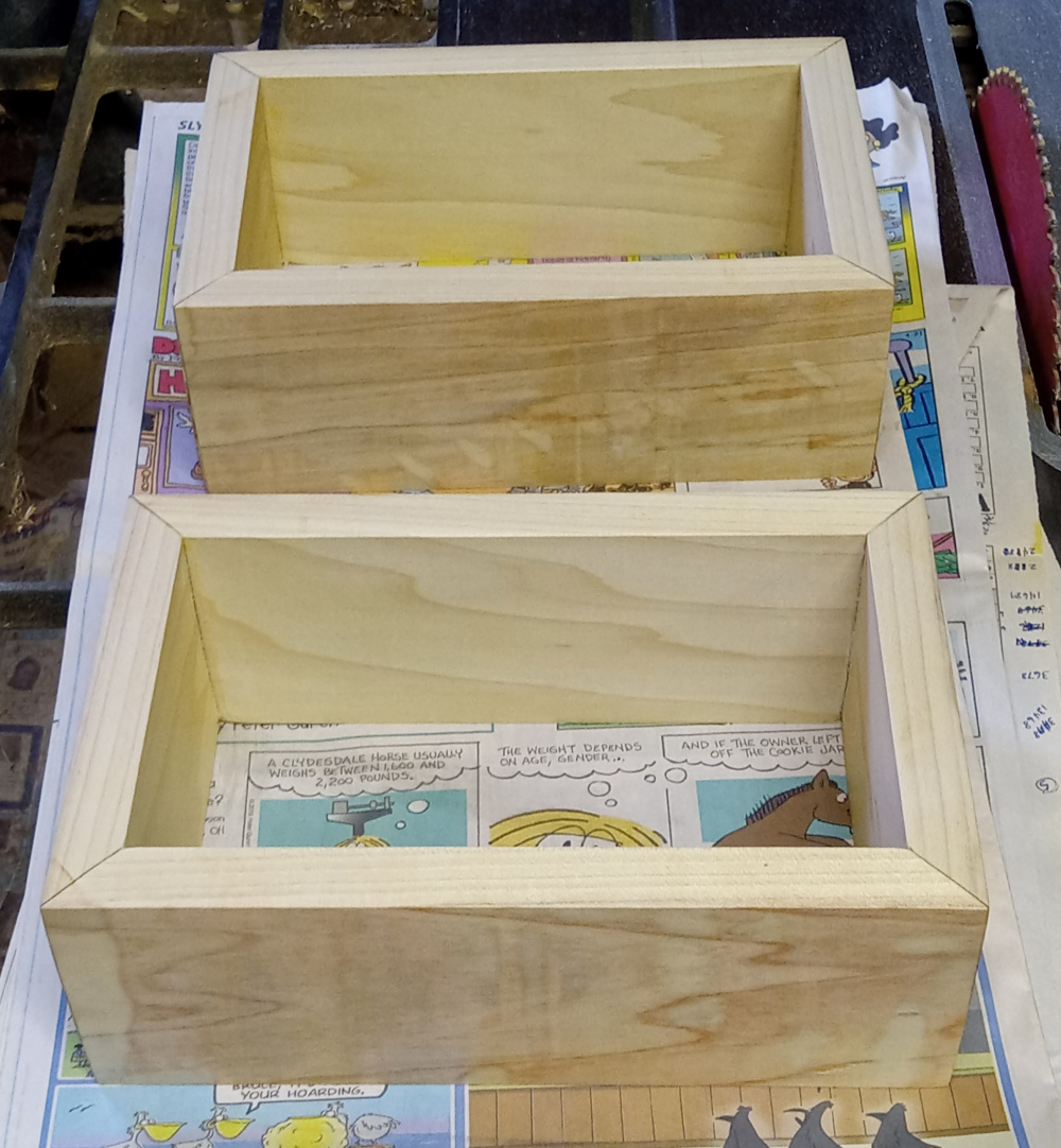
They look pretty good to me for xover boxes.
InDIYana Event Website