Site Links
Howdy, Stranger!
It looks like you're new here. If you want to get involved, click one of these buttons!
Quick Links
Categories
In this Discussion
Who's Online (0)
Twin subs

So I bought a pair of plate amps and a pair of 3" precision ports this last weekend to go with those GRS 12" high excursion drivers.
I'll post preliminary models later since I won't have actual enclosure volume until I get bracing figured out. I suspect it will be around 2.6 cubes or so.
Today I cut all six major panels and mapped out the front baffles. They will be mirrored. The front port is a concession to placement, so don't give me any shit.
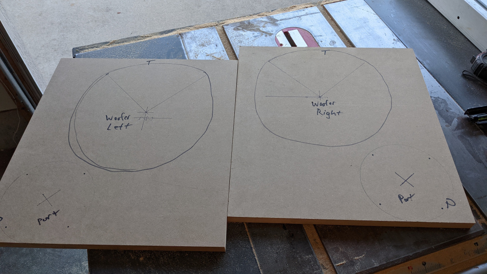
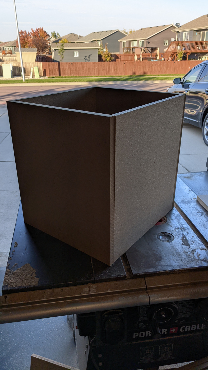
Overall outside dimensions are about 16x17.625x17.625. front and rear baffles are 3/4 MDF. Rest are 5/8" particle board. I used what I had.
Will cut driver, port, and amp openings tomorrow. Mock things up and plan my bracing accordingly.


Comments
LOL @PE. This was $40 when released, already up to $55.
So my net volume is looking to be 2.5 cubic feet +/- 0.1, so I modeled based on 2.5.
Using the Dayton 240W plate amp, which has a 2nd order highpass built in at 20Hz, and the LFE input is set around 150Hz. There were independent measurements posted somewhere at one point, and I remember them.
On that note, a YouTuber named Big D Whiz strapped the Dayton 250W plate amp to his dyno and it fared very well even under an 8 ohm load. I really doubt there is any significant topology differences between the 240 and 250 watt versions. Seems all they did was change the model number and install a toggle switch for boost/no boost. The Dayton measured over 400W "dynamically" - amplifier headroom should not be an issue in this design.
Anyways, I did all modeling based on 240 watts. Since I do not trust PE using the "overhang plus 1/3 top plate" Xmax equation, I measured the top plate on the GRS and found it to be 6mm. I targeted 10.5mm as actual Xmax, and figure the advertised to be mechanical protection. I would love to see how PE verified their XMax claim. In free air sine sweeps at a relatively high input voltage, the driver is pretty clean so they may be telling the truth, but it doesn't matter in this particular design as you will see.
Here is the modeled pass band of this woofer in 2.5 cubes, tuned to 20.4Hz with the high and low pass filters applied. Upper and lowed F3 points are 25hz and 150Hz respectively. I did not do Le modeling since WinISD does not do so correctly, and likely does not impact the roll-off to a significant degree at the expected 60-70 hz crossover point. I chose that tuning frequency for not reason other than it is a 16" port length, which equals my Precision Port without having to trim anything - the end correction is 1/2" per flare according to PP so I'll just throw it in there. F3/6/10 of 25/21/18Hz - this should end up being fairly flat to below 20hz in-room. Boom.
The amplifier will not be working hard, at all, in this design. This is what WinISD predicts will be the load on the amp:
At full amplifier output, this is what we can expect excursion to look like:
As you can see, it does not exceed overhang Xmax until well into infrasonic region, and then only very slightly. If we take PE's advertised as accurate, we are well within Xmax limitation. This driver models very, very well.
Here is the theoretical max SPL:
Peak SPL is almost 101db at 20Hz, and 108db above 40Hz. Again, room loading will extend the maximum SPL on the bottom end.
Vent velocity is a touch high at 29m/s - but that is also at 19.8Hz so I do not anticipate any issues with chuffing under 99% of circumstances. Very little music will excite the port, and in any event I do not sit around listening to 20Hz sine waves at 100db.
I will be finishing up the cabinets sometime today, and they will need some time for the glue to set up - which is time I will use to figure out a finish. Might just wrap them in some black cloth or something, not sure.
Keep in mind, I am building twins - so you can add 3db to the SPL numbers. My Pre/pro does independent bass management for the dual subwoofer outputs, so I should be able to achieve a pretty smooth bass response at our seating position. This is a prototype system for when I build my pair of dual 10" subwoofers using much better drivers.
Those should do a good job of rattling the house a bit")
My take on the PE xmax=overhang+1/3 top plate is just a generous view on usable excursion,
assuming basically the motor can probably effectively drive the coil a little beyond the edge of the plate before flux becomes substantially weak. Although I think they are trying to just stretch the excursion capability numbers and not provide an xmech number, it’s probably a good conservative limit to follow for xmech.
Many basic drivers use the same metric for defining Xmax for years, it's not something new. It is important to understand how Xmax is being defined by the manufacturer, as there is no defined standard convention. Some may be ((coil length - gap length) / 2) + 1/3 gap length, some may just be (coil length - gap length) / 2, or maybe ((coil length - gap length) / 2) + 10%, some may even use klippel definition of 10% THD by BL curve. Neither is "wrong" per se, but knowing how it is being defined is important to place some context to the values.
I dunno, I've been buying drivers for 30 years, and I keep seeing claims that manufacturers routinely claim more than overhang as "xmax".
Not sure I've actually ever seen an example of that short of publishing Klippel data (said data much newer than my experience in this hobby) until PE dropped this. Keep in mind, their new RS ultra high long throw super thumper subs also claim 1/3 top plate xmax, as well.
Great drivers. To bad there almost twice the price they were a month ago.
https://www.jfcomponents.com/
FU PE
Interesting. (coil length - gap length) / 2 Or one side of overhang (same thing) I guess is how I always understood published Xmax to be. The fact that PE published their method makes me think they are trying to get ahead of someone taking one apart and determining the published Xmax to be different of the “reviewer’s” physical measurements of (coil length - gap length) / 2 and making a stink over what they see as false data claims, despite it probably being a perfectly ok tolerance.
Regardless, these are pretty sweet drivers and I’m excited to see how they turn out!
Xmax is just another over-simplification of complex information, similar to Le. There's more to driver performance than just the size of the gap and length of the coil. T/S parameters in combination with BL(x), Kms(x) and Le(x) should be the new standard for manufacturer specs.
I 100% agree, the parameters you mention certainly identify truly linear excursion. Where the oversimplified usage of “xmax” basically identifies general usable travel. I think only special drivers would use those parameters to identify true xmax (and publish the klippel results) because most drivers will fail miserably at testing by those standards.
A basic motor with a standard pole length and no correction for inductance is non symmetrical at the slightest movement, so a published xmax based on true linearity would be 0.1mm. Won’t sell many drivers and isn’t useful data for standard drivers in standard builds, where a person really just needs to know effective coil travel.
I agree with you that published xmax should be linear travel as intended, but should be accompanied with an effective travel number, which is more meaningful in normal builds.
Anyway, my apologies for the derail JR!!!
...finally spent some time on it this evening.
Will finish flush trimming top/bottom tomorrow, then glue most of the remaining bracing in. If not tomorrow night, sometime Sat I will be done with construction. Going to find a nice fabric for top, bottom, and sides and use the satin black paint for front and back.
Hard to see how the bracing all ties in, and in full disclosure I've been Irish style drinking for about two hours now so I'm not able to explain why what I do works, but it does.
Anyways, if I think about it, I'll try to come up with a CAD file showing how I land bracing.
Looking good. I should have hired you to fix the trussing in my attic!
Probably too hot in the attic for wood glue.
Good grief, JR, brace much?
I got dizzy looking at the pictures...
Decided to finish them with some cheap vinyl flooring. Not sure the PSA will hold, so I may supplement with some contact cement and a few brad nails.
It should double as a damping layer, as well. Fairly dense. I need to run to the Menards this morning, now. Shucks.
So after running errands all day and taking a nap, I finally got first layer glued on.
Started with bottom under the assumption I would fuck up learning how to do it, said assumption proved true. I'm not very good at cabinetry, good thing I know how to design a damn crossover.
I have four panels on each sub laminated. I might be painting front/rear baffles in satin black.
The vinyl is not half bad!
Warts and all. I learned quite a bit in this process, I will be doing it again but without texture. The edge trim bit are into it here and there. Gluing it up was a challenge, as well. Will paint front and back tomorrow. Got some cheap Elcon feet coming. Should have them finished by this weekend, if the contact cement is done outgassing anyways.
There is noticably less ringing performing the dubious knuckle rap test, down what it's worth.
I'll experiment with some furniture markers to see if I can hide where my router bit in. The shot where I hogged it out is staying - the port will still seal to the baffle. They will be glued in place.
So anyways, just about done. Still gotta clean the vinyl and see what I can do cover my blems. There is still some outgassing of the glues I used not just to adhere the vinyl, but I used automotive weatherstripping adhesive to secure the ports to the baffle so I want to make sure I don't get the woofers fubar - once bitten. So in this pictures, the woofer is mounted only to make sure the port clears. Maybe Tuesday night I will button them up and get them into the basement.
Early in the process of integrating them into the room:
I dialed just the one in by ear, and cranked it up. These drivers are pretty legit.
Looking good! I think your success with these drivers has jacked the price up. They are now up to $60, but still out of stock.
Well, the good news is with the 10% off everything sale, they are currently priced where they were a week ago before the sale...
Don't get me wrong, they are a great driver but something doesn't sit right with the price creep the last few months on them - availability issues notwithstanding.