Site Links
Howdy, Stranger!
It looks like you're new here. If you want to get involved, click one of these buttons!
Quick Links
Categories
In this Discussion
Who's Online (0)
Introducing: Retro Speako

The basic design concept for this project is a small 3 way mini-tower using some of the best vintage drivers from the 1990's.
Can 30 year old drivers sound as good as some of the best modern drivers? Or will they sound tired and worn out? This project will be my attempt to find out.
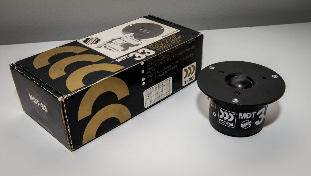
Tweeters: Matched pair of Morel MDT-33 one inch domes (1990). Picked them up used at MWAF at few years ago as a backup set for my existing pair. Spec sheet Fs is 700Hz on these, but I am measuring 883 and 943Hz on one pair and 1400Hz and 1450Hz on my slightly older pair. This is probably due to the ferrofluid drying out. So, my plan will be to clean out what remains of the old ferrofluid & replace it with new stuff. I'll start off with 100uL and adjust as necessary to reach 700Hz.
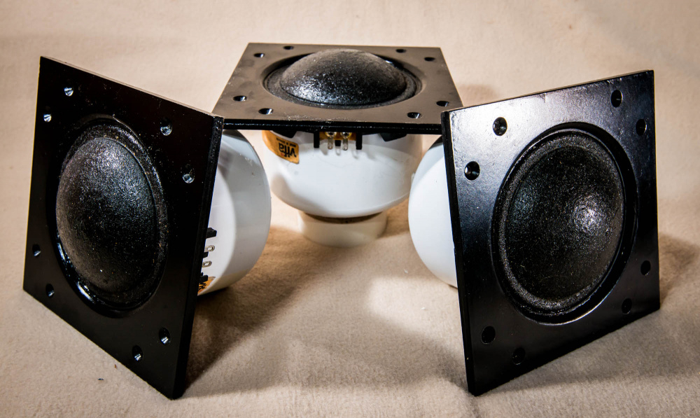
Midrange: Pair of vintage Vifa D75MX-21 three inch domes (guesstimating 1995 or so based on my old Madisound catalogs). Picked these up off the free table at Meniscus a while back (thanks, Dan!). See my "D75 chamber sizing" thread for more info. https://diy.midwestaudio.club/discussion/comment/18004#Comment_18004
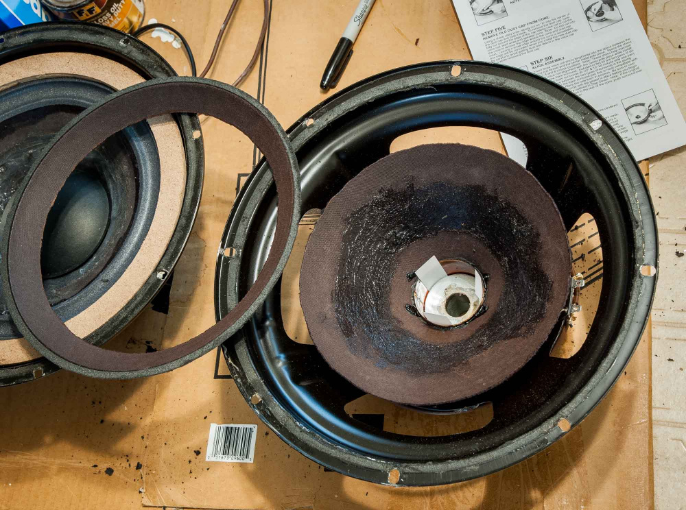
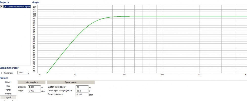
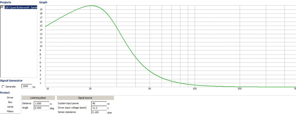
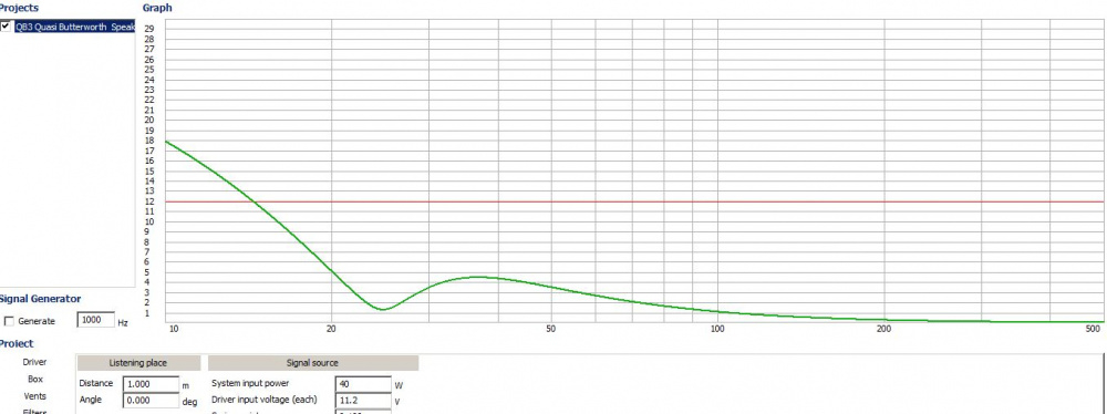
Woofers: Pair of vintage Audio Concepts JC-12 twelve inch woofers (1991). Original TS parameters were roughly Fs 16Hz, Qts .30, Vas 10-15 cu ft., SPL 89dB 1W/1M and Xmax 12mm. The VAS spec measured way too high for a reasonably sized box, so when the foam surrounds rotted out, I cut the original 9.5" diameter paper cones down to 7 inches and then installed PE 10" re-foaming kits. I glued a masonite ring adapter onto the basket to make this work. Average DATS V2 T/S parameters after the mod were: Fs 20Hz, Qts .355, Vas 3.8 cu ft, SPL 86dB 1W/1M. In WinISD, this produces a very good alignment in a 2 cu ft box tuned to 24Hz.
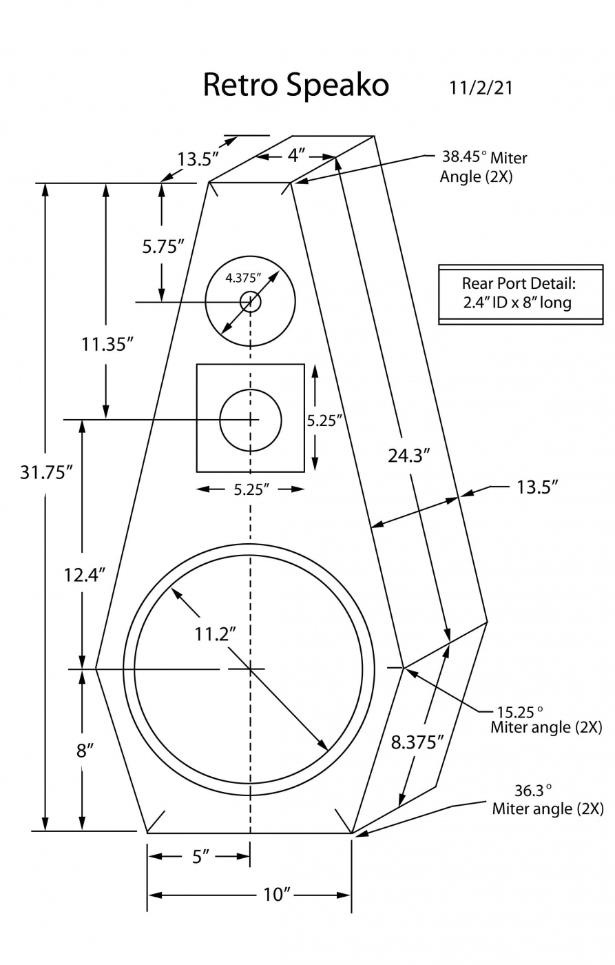
Box: The box shape is going to be a downsized rendition of dcibel's Northern Pikes speakers (or a truncated version of Nick's Pointy speakers). While a little more difficult to build, the non-parallel walls should help to spread out box resonance spikes and excessive diffraction ripple. Type of lumber used will be based on what is available at reasonable prices . I am hoping to do something in a solid wood (poplar, cherry, mahogany, etc.) that looks nice. The box will have a removable back panel for port tuning, re-stuffing, and xover tweaking.
Stands: The speaker will be designed to be placed on top of a 13" high stand. I tried to design it as a floor stander, but didn't like the shape or woofer placement. Also, the cabinet was not deep enough to accommodate an 8" long straight port tube. But with a 13" stand, the cab is deep enough for an 8" port and the woofer will still be about 20" above the floor. This will give me a small amount of floor boundary reinforcement, which, when combined with roughly 3dB of BSC should produce a flat response from 1kHz down to 80Hz when placed well out into the room. The WinISD alignment should fill in the rest, with an F3/6/10 of 28/24/20.
Xover: Based on HD & FR measurements, the mid should be able to handle the 600Hz-4500Hz band. Wolf suggested 600Hz-2500Hz as the sweet spot, so I will be targeting this as my starting point in the design. Using dcibel's "Ideal centre to centre distance" thread recommendation of 1.0 to 1.4X wavelength, I set the center to center distance between tweeter and mid at 5.6 inches, which should be ideal for an xover in the 2500 to 3500Hz range. And to avoid on or off axis peaking at high frequencies, I staggered the tweeter to side and top edge distances by 1.62X (see drawing).
So, off to the big box lumber yard to see what I can find. Will post construction pics as I go along. Bill

Comments
I like where you're going with these!!!
Interesting concept Bill, looking forward to the results.
Very clever, cutting those cones down! I'm betting these will sound great - like all of your projects.
I think this will sound good! Interesting thing your woofer mods are...
InDIYana Event Website
I love the old school monkey coffin design, but with your mad shop skills, of course the box at least will be a work of art, and not anywhere close to a "boring" rectangle.
Interesting speaker! I'm glad that my posts have provided some inspiration, so I am excited to see how this turns out.
On the "ideal driver spacing", the recent information provided by Kimmo on that "rule" is that it applies to a situation where you have a normal midrange and dome tweeter with flat face plate, and the crossover is a "common" LR 24dB/oct type. So some assumptions are made based on the common interaction between drivers, crossover frequency and directivity. Once you stray beyond those constraints, the ideal driver separation and crossover frequency can be determined on a case by case basis with VituixCAD.
Insight on the ideal driver separation can be determined easily with VituixCAD once you have complete 360 degrees of measured driver data. Simply load the driver data into VituixCAD, use the active crossover and PEQ blocks to provide a crossover and nice flat on-axis response, then adjust the y axis distance between drivers until you get the best balance between on-axis, in-room, power response, etc.
In the case of my Northern Pikes speaker, the separation between midrange and tweeter ended up at 1.08X the crossover frequency for a great in-room response, but I used an AMT there, and the on-axis has a rising response to help cope with the high directivity of the larger AMT. End result - it's currently my favourite speaker to listen to.
Thanks, everyone, for all the encouraging comments on my design. Table saw is ready to go with a new blade installed. I borrowed the idea of cutting the cone down from Henry Kloss (the K of KLH and founder of Advent Corporation). This is what he did on the original Large Advent Loudspeaker system. He installed a 9 inch cone into a twelve inch woofer basket using a thin phenolic ring to make up the difference. This is how he got deep bass extension in a small 1.6 cu ft box.
dcibel, thanks for the tips on using VituixCAD. I will be switching over to this software package for this buiild and for the Indy competition. This is a very nice program and I am liking it alot. I will not, however, be able to do spinorama modelling until I get a two channel system setup with new mic, new external sound card, connection jig, phantom power supply, etc. I have SoundEasy V20, so I will be using that software package to make the measurements, and then transferring the FRD's to VituixCAD to do spinorama, power response, and directivity index simulations. ZMA's will be captured with my DATS V2.
But before I get my new 2 channel setup completed, I will be using single channel OmniMic FRDs, loading them into VituixCAD and running simple single-axis simulations. I will also be doing a limited number of polar simulations at 15, 30, 45H and maybe 5, 10, 15V. It is possible to do this in VituixCAD by taking T+W measurements for each polar angle and calculating offsets for each polar angle. You would then create tweeter and woofer drivers for each polar angle and then attach the appropriate polar FRD to the appropriate polar tweeter or woofer driver. A different offset can then be entered for each polar angle. Kind of clunky and time consuming, but it works. This will not give me good power response or DI information, but, once this is set up, I will be able to quickly click drivers to different polar angles to see how my crossover changes are affecting both on and off-axis models.
Bill
Have to be careful when editing my posts. I went back in to correct the spelling on "phonelic" to "phenolic" and this worked fine. But then I simply added a space between paragraphs (for clarity), and then the font size decreased dramatically. In addition, all the individual sentence carriage returns disappeared (each paragraph became one long sentence running off the screen with very small fonts). So I then went back in and deleted the spaces that I had added between paragraphs, and then the fonts and carriage returns returned to normal. Strange. So, I guess if you edit, don't add spaces anywhere. It will mess things up.
Great, I helped develop the Measurement for SoundEasy tutorial for VituixCAD. It simply provides the same instruction as ARTA but using the impulse response export for each measurement from SoundEasy. The benefit is that you don't need to get very in depth with SE, as it's just being used to create the raw measurement, the IR->FR processing, even the mic calibration will all be completed within VituixCAD.
Short answer is yes, providing single channel measurement data in VituixCAD provides no more insight to the speaker performance than you would get from Xsim, although the software is a fair bit nicer to use IMO and you still have the optimizer available but will be limited to the single axis of optimization. Understanding those limitations, yes it can be done, but is not recommended as you miss out on the best features that VituixCAD has to offer.
The process is simple, take the 3 measurements as you normally would of midrange, tweeter, then both together. In VituixCAD, the delay determination is automated by going to Tools -> Auxiliary -> Time Align. I would uncheck the MP "min phase" check boxes to use the as-measured phase data. Hit the solve button and if you've done everything right you should arrive at a delay value with minimal error.
You can then proceed with near field and diffraction sim, use the merger tool to bring it all together. The merger tool will retain the as-measured phase of the far field data so the delay value will remain unchanged. To use the delay, simply load in your measurements to the driver data, leave the driver physical locations as 0,0,0 in the crossover, and enter the delay under the driver settings at the bottom.
You can then re-do this process with another set of 3 measurements for any angle that you would want to inspect. Each off-axis angle can be expected to have a different delay value as the acoustic centre moves around with the listening angle, which is why a 2 channel setup is the only way to get reliable data in a simple manner. As well the 2 channel method allows you to measure on-axis with each driver
Once you have a crossover designed a built, you can measure all off-axis angles for the entire speaker as a whole and load that data into VituixCAD to generate the spinorama for the entire speaker, but for the design process you are rather limited in functionality.
(FWIW I edit my posts often to correct typos or add detail and have never had a problem. This comment is an edit)
Thanks for all the excellent tips, dcibel. I think I am finally beginning to understand how all this stuff really works. It is nice to see that when you merge NF+FF using VituixCAD's merger tool, the as measured phase data is retained. This means that, when using a good two channel microphone measurement setup, there is no need to extract minimum phase or do the 3 measurement routine at all (i.e., no need for offsets). This really streamlines the entire process!
I can also use VituixCAD's merger tool to bring in the Allison room boundary reinforcement equations. Using Jeff Bagby's BDBS spreadsheet, I can create an adjustment FRD to account for the woofer to floor distance. Then I can merge this into the VituixCAD model to get a much better picture of how the baffle step and floor boundary affect each other.
With the 2-channel system is that you can effectively forget about minimum phase altogether, it's not necessary, only relative phase is important. You can also measure each individual driver on it's own axis, creating that 360 degree measurement bubble for complete and accurate insight of off-axis performance. The only item that needs to remain constant is the distance from mic to speaker baffle, and the FFT window start time when processing the measurements.
As an aside: Min phase isn't strictly necessary for single channel measurements either, which is why I suggested above to use the as-measured phase even for the Omnimic measurments. The 3 measurement delay determination may arrive at a different value when using measured data vs min phase, but it will be the correct value for either method. The "benefit" of min phase determination is more the Hilbert-Bode transform (HBT) to apply "tails" which can effectively remove the noise floor and fill in data beyond the measured frequency range, but the phase changes here are generally at the frequency extents, not the in-band frequencies that you would apply a crossover. VituixCAD instructions skip over min phase and HBT completely as "simply not necessary", so just make sure to take measurements at a reasonable volume in a quiet space, if using MLS in SoundEasy you can run multiple measurements with averaging to lower the noise floor to a minimum.
You will notice as well the "floor reflection" option in VituixCAD's diffraction tool. It includes a absorption factor as well, as most calculations in this regards assume a 100% reflective surface, where the reality is some combination of reflection, absorption, and transmission. I have found absorption factor of 5-8dB is about right for my space, so for a woofer right at floor level such as my Northern Pike, this results in a BSC of 2-3dB instead of the normal 5-6dB.
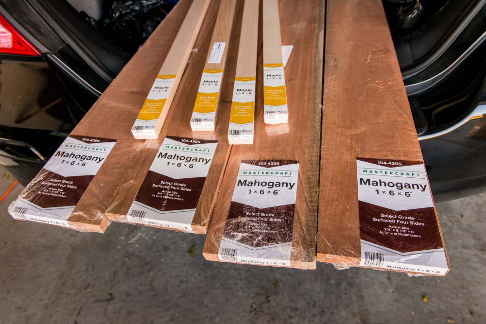
Just got back from the big box lumber yard. Found some pre-finished mahogany and maple boards at very reasonable prices. Bought enough to do the sides and tops of both cabs. My plan will be to glue a single 1.5" maple board between two 5.5" mahogany boards for a total cabinet depth of 12.5 inches. Mahogany is very soft compared to maple, so the expansion and contraction rates will be different. Hopefully this will not cause a problem down the road.
Mahogany is pretty dimensionally stable. The maple inlay on my mahogany baffles hasn’t budged anyway so I’m sure you’ll be fine, and the two go really well together")
First step is to carefully layout the boards for the best grain pattern and the least amount of warpage. I marked each board's relative position on the cabinet. The plan is to first cut each board slightly oversized and then glue the boards together in sets of 3. Once the glue has dried I will trim the boards down to exact size on all 4 edges. Two of the edges will be mitered. In this way, I will be able to correct for the slight amount of warpage in the original boards.
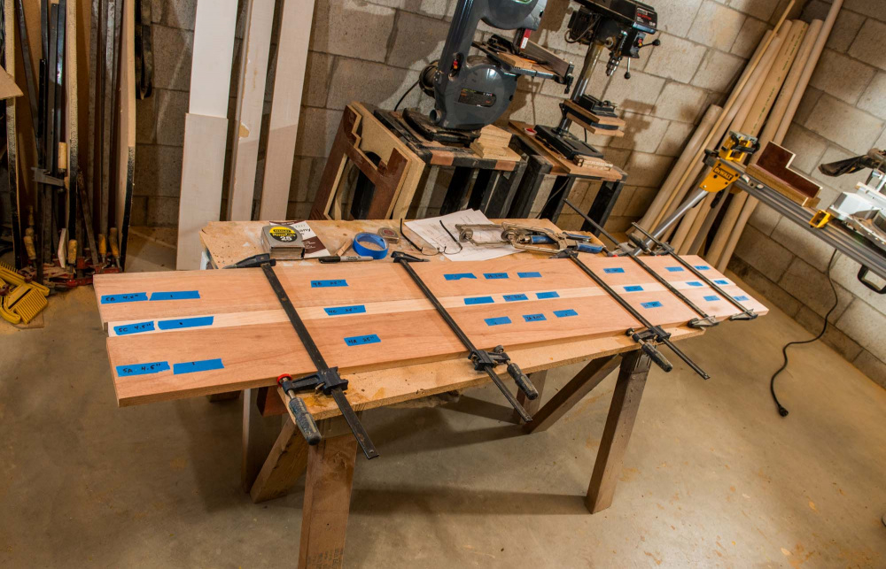
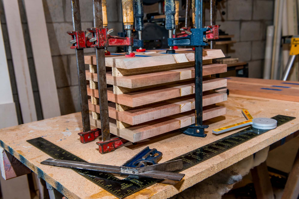
Progress has been slow. Lots of time to cut up all the panels and then glue and clamp them together against a rigid, flat surface. Each board is made up of 3 sections: 5.5" mahogany + 1.5" maple + 5.5" mahogany for a total speaker depth of 12.5". I left each multi-section board in the clamps for about 3 hours, then transferred them to a small lumber drying rack to complete the curing process. In the photo, the two top panels are for the cabinet tops and the four lower side panels are positioned between spacers below. I placed two thin 3.4" spacer sticks between each panel to keep things flat during the cure. I will be leaving these in the clamps for at least 72 hours, then moving on to the much larger upper side panels.
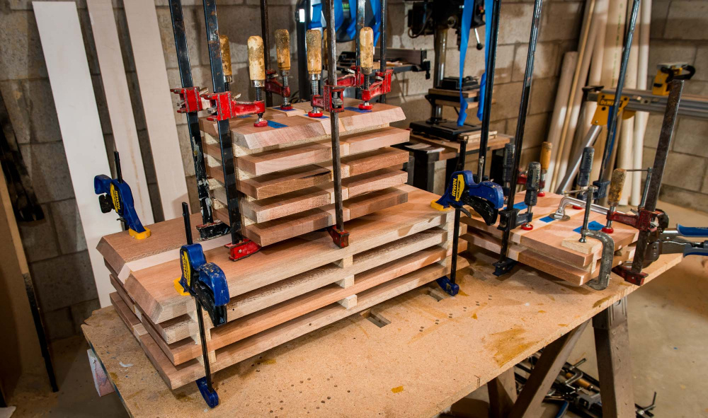
I now have all the side panels, tops, and bottoms glued up and firmly re-clamped into my curing/drying racks. I temporarily removed 4 clamps on the larger side panels so I could fit everything into one photo. I am now beginning to cut the edge bevels, placing the boards back into the drying racks between cuts. Then once I have all the bevels cut, I'll wait about 72 hours or so and then glue up the cabinet. I going to use the folded tape method using gorilla tape (not masking or box tape).
Menards hardwood for the win!
I've used Menards Mastercraft hardwood boards many times for speaker baffles and amp cases and they are a good value. But like ANY wood product from Menards you have to sort through their entire stock to find the good looking and straight ones you want. I look forward to watching your progress on this project.
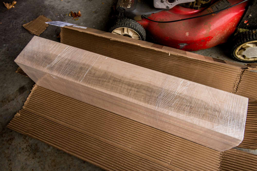
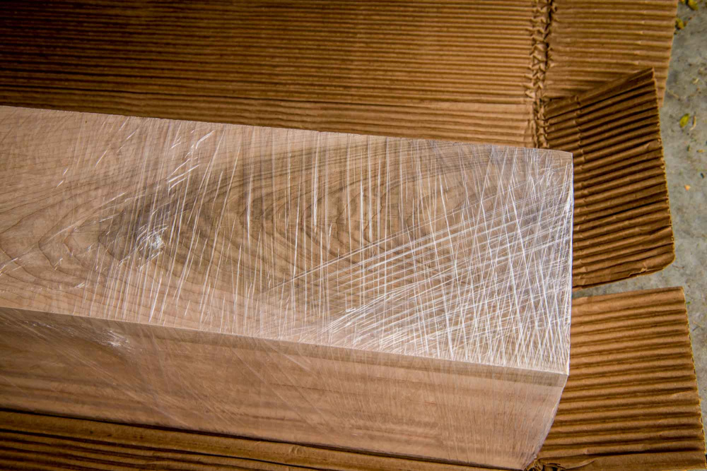
Thanks, Craig. I went through quite a few, but was able to find 4 good ones. These boards are finished S4S (surfaced on 4 sides) and then sealed in shrink wrap. But then the shrink wrap gets all busted up during delivery or by customers. Noone seems to understand the importance of the shrink wrap. To keep the boards from warping, they either need to be sealed on all sides or completely open to the atmosphere on all sides.
My experience with Menards hardwood is they offer little to no consistency in dimension, I'm sure you will have to plane it out.
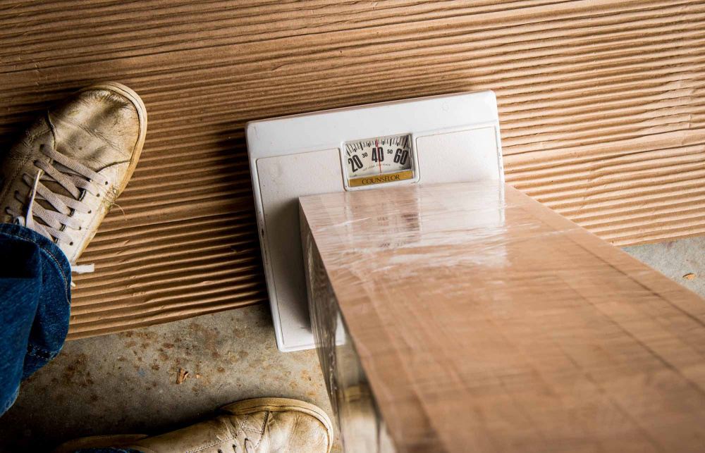
Correct. There is a little variation from board to board that will need to be flattened out. The thickness of my boards varied from about 0.75" to 0.79" or so using my dial calipers. The 5.5" and 1.5" widths were spot on, so hopefully I will not have problems during the glue up.
You are such a wood artist! At first I couldn't figure out why you were clamping so long, then I realized that you were trying to minimize warpage as the various boards adjusted to the RH in your house. Saves on more problems later.....
Correct. I'm trying to follow the "care of wood" techniques recommended by Ocooch Hardwoods. Here is a link: https://ocoochhardwoods.com/care-of-wood/
I keep a dehumidifier running year round in my basement, but it is still more humid and about 10 degrees cooler than upstairs. So, after gluing the boards together and taking photos, I moved the drying racks upstairs in an attempt to "acclimate" the wood before the final glue up.
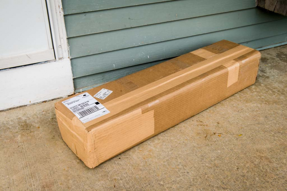
UPS just dropped off my Ocooch Hardwoods order. 40 lbs of curly maple, enough to do the backs and baffles on both speakers. No shipping damage. All dimensions measure spot on. Freshly milled with no signs of cupping or twisting. All boards tightly wrapped in shrink wrap. At first glance, the boards appear to have some very interesting grain patterns for me to work with. Should look really nice when the finish goes on.
Yumy. Oil based poly, Rubio, BLO, etc. will make the grain pop. Make sure you do some test pieces. Grain view will flop depending on which direction you are looking. Just finished some shelving where I edged plywood with some curly and flame maple.
Yup orientation is key, learned that the hard way on my first speaker build.
Good tip. Can you see this grain flip-flopping situation before you apply the finish? The 10 boards are 6" x 36" and my plan is to glue 8 of them into pairs, giving me 4 panels measuring 12 x 36. The remaining 2 boards will be used as filler sticks to cover the 15" wider baffle area by the woofers.
Since the cabinets are only 32 inches high, I could carefully mark all the boards with masking tape on each end for ID purposes and then cut 4 inches off the end of each of the 10 boards. I could then apply finish to these short 4 x 6" boards to check for grain flip flopping. How does that sound? Or am I missing something?
You can use some mineral spirits or a damp cloth.
Mineral spirits for the win!")
Acetone evaporates much quicker.