I think it would look cool if the tube was going out the top. You could mount larger components like capacitors on the bottom to get the tube closer to the top.
@kenrhodes said:
I think it would look cool if the tube was going out the top. You could mount larger components like capacitors on the bottom to get the tube closer to the top.
Good idea. I took some measurements and discovered that I can raise the PCB another 3/4" before running into any capacitor or heat sink clearance problems. The tallest item on the PCB, other than the tubes, is the filament power supply heatsink for the 7806 regulator. But if I replace that heatsink with a shorter one, I can raise the PCB as much as 1.25" with no problems.
@Tom_S said:
Looks good! I have some shaft extensions and bushings I could send you, but they won't work with that knurled shaft.
Ya, the slotted, knurled shaft would be crushed by the set screw. My plan is to use some inexpensive "Hillman Fastener" type nylon sleeves and bushings that have an approximate 1/4" ID. I'll cut a slot in the nylon sleeve and slip it over the knurled shaft and extension, then pour some 5 minute epoxy into the slot and joint. If I can keep everything in perfect alignment as the epoxy sets, I should be good to go.
Very warm? sure. Not so hot that I couldn't leave my finger there indefinitely. I understand, it comes with the heatsink so why not use it right? But if it is a space issue, and leaving it bare makes you uncomfortable; I'd say mounting it to the chassis should give it a nice cushy life.
Thanks, Drew. I agree. It looks like the tall heatsink supplied with the kit is overkill. I have 3 other much shorter T0-220 style heatsinks that I can substitute. Any one of them will fit the existing PCB space and solve the problem.
Edit: Oooops, looks like I have the 7806 in backwards on the pic. It is not soldered in place yet. I accidently put it in backwards before I snapped the photo.
Here is a visual comparison of the original tall heatsink verses a much shorter one. This will allow me to push the PCB up an additional 1/2" or so for a nice tube glowing effect. Almost ready to give it the smoke test.
@Nicholas_23 said:
Bill , could you have reversed the tube socket install to the bottom of the board to bring those tube out of the chassis a little more? Not sure if that makes sense.
I thought about that too, but the pinout for the tubes would be reversed. Probably easier to just mount the other tall parts from underneath instead.
If the jacks were left off and wired in remotely, could add input caps in-line. Though I don't know enough about tubes. Is grid impedance influenced by the other operating voltages? If not the original kit updated value of 3.3uf would work? But maybe higher voltage spec to withstand a worse case scenario.
A big thanks to DrewsBrews for giving me this circuit - I don't know too much about tube circuits or any circuits in general. So looking to see if I should go ahead and build it as is or some improvements can be made.
@DrewsBrews said:
If the jacks were left off and wired in remotely, could add input caps in-line. Though I don't know enough about tubes. Is grid impedance influenced by the other operating voltages? If not the original kit updated value of 3.3uf would work? But maybe higher voltage spec to withstand a worse case scenario.
My understanding would be that the input impedance of this preamp would be the 50K pot in parallel with the 1 meg grid resistor (1/((1/1000000+1/50000)) = 47.619K ohms. This resistive input load would be modified somewhat at very high frequencies by the 6J1 tube's plate to grid (miller effect) and grid to cathode capacitances.
So if you placed the input capacitor externally, then the cap would basically see a 47.619K load. Using a 3.3uF input cap, the -3dB low frequency roll off would be 1/(6.28 x 47619 x .0000033) = 1.01Hz. This is overkill. A 1uF cap should be more than enough: 1/(6.28 x 47619 x .000001) = 3.3Hz (-3dB).
On the original 6J1 preamp kit, we did not need to boost the input cap from 1uF to 3.3uF (C9, C11). We could have left it at 1uF and experienced no roll off problems (my mistake). It was the output 1uF cap (C10, C12), driving into a 10K load, that caused excessive roll off. So only the output cap needed to be boosted to 3.3uF.
1/(6.28 x 10000 x .000001) = 15.9Hz (-3dB). So 20Hz would be rolled off by about 2.5dB or so.
@ani_101 said:
Bill, are you doing any modifications to this circuit?
No plans to modify, other than, as Drew indicated above, adding an input cap to block DC from the grid. I am going to experiment using a 1uF 100V panasonic polyester in series with the input jacks.
EDIT: Correction. The 6.4vac below should be 6.8vac.
Powered it up with variac and dim bulb today. No smoke or fireworks. Everything checked out very good except the filament supply voltage. I think I might have a defective full wave bridge rectifier on my heater supply.
Drew, what voltage did you get on your filament supply? I was getting 6.4vac [correction: 6.8vac] on the two white xformer leads, then 7.15vdc after the full wave bridge, then an unregulated 5.43vdc after the LM7806. The 5.43vdc had 134mv of AC ripple riding on it. Then I switched the filament supply over to a 12vac Radio Shack xformer, and was able to get 9.36vac on the inputs by using an 8 ohm 10W dropping resistor in series with one leg of the secondary winding. So now I get 9.36vac at the input, then 9.147vdc after the full wave bridge rectifier, then 5.923vdc after the LM7806 regulator. The 5.923vdc only has 2.3mv of AC ripple riding on it. Heatsink gets warm, but not hot.
@DrewsBrews , here are my voltages by 6J1 tube pin, in case you want to compare it to your build. These are all dc voltage to ground measurements using minigrabbers and my DMM. No signal input, volume control turned all the way down (shorted input). Incoming line voltage was 120vac for all tests. B+ measured 250.2 to 253.3vdc during the testing process.
Pin #1: 0.000vdc (grid) for both channels
Pin #2: 2.44vdc for left channel, 2.71vdc for right channel
Pin #3: 5.43vdc for left channel, 5.47vdc for right channel (using the ali express xformer)
Pin #4: 0.0006vdc for left channel, .0013vdc for right channel
Pin #5: 130.65vdc for left channel, 117.22vdc for right channel
Pin #6: 130.65vdc for left channel, 117.22vdc for right channel
Pin #7: 2.44vdc for left channel, 2.72vdc for right channel
Based on the above, the tube grid is biased at a negative 2.72vdc with respect to the cathode. The idle current flowing through the tube is therefore 2.71ma.
Since I didn't really care about the stock Chinese tubes I just made sure there was no dc on the inputs or outputs before hooking it up to confirm it made sound. I think I did probe the secondary voltages to be sure things weren't way out of wack but I don't remember any numbers. I'll see if I can do some more probing.
Yeah sounds like the 7ish volts is a little too low to allow the regulator to do it's best job. Letting more ripple through. Confirmed since your higher input voltage test puts the output closer to rated 6v. Though is it audible? Is 5.4v too low for the heaters?
I played several music tracks and did not notice any hum caused by this. The 134mv AC ripple on the 5.43vdc is only about 2%, which is not too bad. Probably inaudible.
Yeah sounds like the 7ish volts is a little too low to allow the regulator to do it's best job. Letting more ripple through. Confirmed since your higher input voltage test puts the output closer to rated 6v. Though is it audible? Is 5.4v too low for the heaters?
It seems to work OK at 5.4vdc. This is about 15% below the spec of 6.3vdc. Tubes will probably last longer this way. The tube's transconductance will be somewhat lower when operated at 5.4vdc. This will raise the output impedance of the circuit slightly, but will probably have no effect on either the overall gain or frequency response. I could do some spot FR tests with my scope to verify this. Regardless, I would still like to get the voltage up to 6 and eliminate the ripple.
I thought that perhaps I had a defective full wave bridge rectifier in the filament power supply that was causing an excessive voltage drop. So I removed it and soldering in a different bridge rectifier. The measured voltages, however, remained the same. So I think the bridge rectifier is OK and working like it should. I tested the circuit some more by parallelling 2000uF of additional filter capacitance across the main 3300uF filter cap, boosting it to 5300uF total. This reduced the AC ripple by about 30%, but the output voltage remained at 7.15vdc before the 7806 regulator and 5.4vdc after the regulator.
I think I may also try ordering a 6 or 15 amp bridge rectifier from mouser. If it is small enough to fit the spot on the circuit board, maybe it will have less forward voltage drop under full load conditions. The standard diode drop of .6 volts per diode (totalling 1.2 volts drop for a full wave bridge) would seem to indicate that we should be getting about 8.4vdc before the 7806 regulator, not my measured 7.15vdc. (ie., 6.8vac input x 1.414 = 9.6 - 1.2 = 8.4). But this might be the voltage obtained with no load. Each tube draws about 170ma, so there may be additional losses caused by the 340ma load.
Or it may be that I am simply using the wrong set of equations for calculating the resulting DC voltage that is produced by a full wave bridge rectifier. Egg on face! Gotta do the math!!! I found a youtube vid where the author shows all the proper calculations and when I use his set of equations they result in a perfect match to my actual measuements! Go figure!
Input: 6.8vac coming from xformer under full load
Vpeak at input of bridge: 6.8 / .707 = 9.62vdc
(This must be reduced by 2 diode drops to get the Vpeak at the output of the bridge. The diode drops measured about 0.57 each x 2 = 1.14)
Vpeak at output of bridge: 9.62 - 1.14v = 8.48vdc
DC output = (2 x Vpeak) / 3.14 = 5.40vdc
I think the "DC output" number just coincidentally is similar to the regulator output at that voltage.
That calculation is purely an average line for the unfiltered rectified wave output. A line where the area of the "peaks" above the line matches that area of the "valleys" below the line.
Voltage regulators have a minimum voltage input required to produce the desired output. Quick research tells me this minimum can be as high as 3v diffrence, likely more or less depending on the design. If you are supplying below the threshold, then it's output will not be regulated so well. That is what I think is going on in this case... the 7.x volts is not quite high enough for the regulator to supply a steady 6v. I imagine the higher the input voltage (to a point), the better it can do at supplying a steady voltage. Though the price for that is paid in higher VA rated transformer and higher heat load.
Sorry for the confusion, but I did some more breadboard testing and I think I discovered why I am only getting 7.15vdc after the full wave rectifier. I simply have a defective LM7806 regulator chip. As soon as I order a new one and replace it, the circuit should work just fine. I reached this conclusion by testing this same circuit on my breadboard, but with the LM7806 chip bypassed. I fed the 6vac transformer secondary winding directly to the full wave bridge. Then I used 3200uF of filtering at the output of the bridge, which is very close to the 3300uF cap used on the PCB. I loaded the circuit down with a 20 ohm, 20W resistor, which is the same load as connecting two 6J1 filaments in parallel. And I get 9.1vdc at the output. This is more than enough to properly bias an LM7806 chip.
Again, sorry for the confusion. I think the final math calculation in the video that I posted above showing 5.4vdc probably is, as you have suggested, just a coincidence.
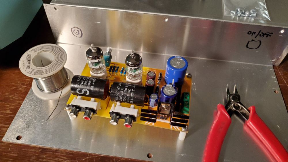
The ceramic tube socket pins are very tight fitting. So whenever I would install a different 6J1 tube in the center socket, the PCB board would actually flex and push down slightly in the center. I was concerned that this might cause PCB traces to crack over time, so I added two additional standdoffs for better support. I used JB weld to epoxy one of them in place and then drilled a new mounting hole for the other one. Now there is absolutely no PCB board flexing when I swap out tubes.
Yep I noticed one of the standoffs in a previous pic. Good idea!
As another datapoint.. On my junky dmm I get 6.9v, and 5.2v across the filter caps before and after the LM7806. So pretty close to yours, just consistently lower so probably meter variance. If there is anything not right, it is likely the way these parts were manufactured (IE cheap knockoff) which would not be surprising.
I do get 6.3vac right off the transformer while it is still hooked up to the circuit. Which should be 8.8v peak.
Should we move this to another thread (asking, not necessarily suggesting)? It wasn't my intention to steal the thunder of the original kit, just wanted to further explore the 6J1 tube. See if higher voltage realy has anything to offer.
Comments
I think it would look cool if the tube was going out the top. You could mount larger components like capacitors on the bottom to get the tube closer to the top.
Yep, I like to see the glowy things. Maybe put some copper sheet between the tranx and component board?
Looks good! I have some shaft extensions and bushings I could send you, but they won't work with that knurled shaft.
Good idea. I took some measurements and discovered that I can raise the PCB another 3/4" before running into any capacitor or heat sink clearance problems. The tallest item on the PCB, other than the tubes, is the filament power supply heatsink for the 7806 regulator. But if I replace that heatsink with a shorter one, I can raise the PCB as much as 1.25" with no problems.
And put a couple small holes in the sheet to route the wires through. Would copper be better than aluminum or steel? Copper is kind of expensive.
Ya, the slotted, knurled shaft would be crushed by the set screw. My plan is to use some inexpensive "Hillman Fastener" type nylon sleeves and bushings that have an approximate 1/4" ID. I'll cut a slot in the nylon sleeve and slip it over the knurled shaft and extension, then pour some 5 minute epoxy into the slot and joint. If I can keep everything in perfect alignment as the epoxy sets, I should be good to go.
I have seen people use the adhesive lined heatshrink tubing and zip ties to couple shafts.
I'd use whatever was laying around.
gimme a sec...
Very warm? sure. Not so hot that I couldn't leave my finger there indefinitely. I understand, it comes with the heatsink so why not use it right? But if it is a space issue, and leaving it bare makes you uncomfortable; I'd say mounting it to the chassis should give it a nice cushy life.
Thanks, Drew. I agree. It looks like the tall heatsink supplied with the kit is overkill. I have 3 other much shorter T0-220 style heatsinks that I can substitute. Any one of them will fit the existing PCB space and solve the problem.
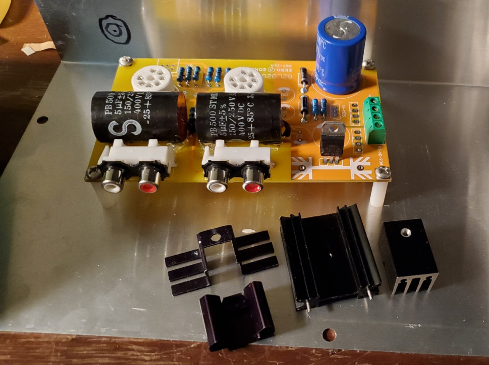
Edit: Oooops, looks like I have the 7806 in backwards on the pic. It is not soldered in place yet. I accidently put it in backwards before I snapped the photo.
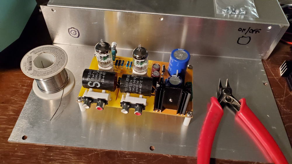
Here is a visual comparison of the original tall heatsink verses a much shorter one. This will allow me to push the PCB up an additional 1/2" or so for a nice tube glowing effect. Almost ready to give it the smoke test.
Original tall heatsink:
Smaller, short heatsink:
Looking good!
I thought about that too, but the pinout for the tubes would be reversed. Probably easier to just mount the other tall parts from underneath instead.
Another possibility would be to install two Jemosa 7 pin tube socket savers. This would raise the tubes an additional 3/4" above the PCB:
https://www.amazon.com/JEMOSA-Vacuum-Socket-Vintage-Amplifier/dp/B0B4Z2B233/ref=mp_s_a_1_10?dib=eyJ2IjoiMSJ9.NuAAqSeqOixqf4jHlwAd2RgR2np0GrgA8VHnwXkVpBaYhXHhyz6Ds-izsVbcTQhBz7NyLgIecrRtaDStnq58i-mhENRGnhtbmOMCB04ZJazXl05llIkpbSATsPrzUt450WlYuF_6eLe2uL12Iu_delGY7UOn3rY4AcgN4EA-AL653_xrzGOJtbfZXxVmTxSKCK9wNmtz4nBoA5lI9WYWGQ.Axg5sko15wLDfb1HvqOXMXvmZDC8PEoOMCCKZzOtvHs&dib_tag=se&keywords=7+pin+tube+socket&qid=1714525047&sr=8-10
Bill, are you doing any modifications to this circuit?
If the jacks were left off and wired in remotely, could add input caps in-line. Though I don't know enough about tubes. Is grid impedance influenced by the other operating voltages? If not the original kit updated value of 3.3uf would work? But maybe higher voltage spec to withstand a worse case scenario.
A big thanks to DrewsBrews for giving me this circuit - I don't know too much about tube circuits or any circuits in general. So looking to see if I should go ahead and build it as is or some improvements can be made.
My understanding would be that the input impedance of this preamp would be the 50K pot in parallel with the 1 meg grid resistor (1/((1/1000000+1/50000)) = 47.619K ohms. This resistive input load would be modified somewhat at very high frequencies by the 6J1 tube's plate to grid (miller effect) and grid to cathode capacitances.
So if you placed the input capacitor externally, then the cap would basically see a 47.619K load. Using a 3.3uF input cap, the -3dB low frequency roll off would be 1/(6.28 x 47619 x .0000033) = 1.01Hz. This is overkill. A 1uF cap should be more than enough: 1/(6.28 x 47619 x .000001) = 3.3Hz (-3dB).
On the original 6J1 preamp kit, we did not need to boost the input cap from 1uF to 3.3uF (C9, C11). We could have left it at 1uF and experienced no roll off problems (my mistake). It was the output 1uF cap (C10, C12), driving into a 10K load, that caused excessive roll off. So only the output cap needed to be boosted to 3.3uF.
1/(6.28 x 10000 x .000001) = 15.9Hz (-3dB). So 20Hz would be rolled off by about 2.5dB or so.
No plans to modify, other than, as Drew indicated above, adding an input cap to block DC from the grid. I am going to experiment using a 1uF 100V panasonic polyester in series with the input jacks.
https://www.mouser.com/ProductDetail/Panasonic/ECQ-E1105JFA?qs=E//hvbtCqpP%2BP9rxjtD1Tw==
Thanks, Bill, let us know what works best - will build accordingly
EDIT: Correction. The 6.4vac below should be 6.8vac.
Powered it up with variac and dim bulb today. No smoke or fireworks. Everything checked out very good except the filament supply voltage. I think I might have a defective full wave bridge rectifier on my heater supply.
Drew, what voltage did you get on your filament supply? I was getting 6.4vac [correction: 6.8vac] on the two white xformer leads, then 7.15vdc after the full wave bridge, then an unregulated 5.43vdc after the LM7806. The 5.43vdc had 134mv of AC ripple riding on it. Then I switched the filament supply over to a 12vac Radio Shack xformer, and was able to get 9.36vac on the inputs by using an 8 ohm 10W dropping resistor in series with one leg of the secondary winding. So now I get 9.36vac at the input, then 9.147vdc after the full wave bridge rectifier, then 5.923vdc after the LM7806 regulator. The 5.923vdc only has 2.3mv of AC ripple riding on it. Heatsink gets warm, but not hot.
@DrewsBrews , here are my voltages by 6J1 tube pin, in case you want to compare it to your build. These are all dc voltage to ground measurements using minigrabbers and my DMM. No signal input, volume control turned all the way down (shorted input). Incoming line voltage was 120vac for all tests. B+ measured 250.2 to 253.3vdc during the testing process.
Pin #1: 0.000vdc (grid) for both channels
Pin #2: 2.44vdc for left channel, 2.71vdc for right channel
Pin #3: 5.43vdc for left channel, 5.47vdc for right channel (using the ali express xformer)
Pin #4: 0.0006vdc for left channel, .0013vdc for right channel
Pin #5: 130.65vdc for left channel, 117.22vdc for right channel
Pin #6: 130.65vdc for left channel, 117.22vdc for right channel
Pin #7: 2.44vdc for left channel, 2.72vdc for right channel
Based on the above, the tube grid is biased at a negative 2.72vdc with respect to the cathode. The idle current flowing through the tube is therefore 2.71ma.
Since I didn't really care about the stock Chinese tubes I just made sure there was no dc on the inputs or outputs before hooking it up to confirm it made sound. I think I did probe the secondary voltages to be sure things weren't way out of wack but I don't remember any numbers. I'll see if I can do some more probing.
Yeah sounds like the 7ish volts is a little too low to allow the regulator to do it's best job. Letting more ripple through. Confirmed since your higher input voltage test puts the output closer to rated 6v. Though is it audible? Is 5.4v too low for the heaters?
I played several music tracks and did not notice any hum caused by this. The 134mv AC ripple on the 5.43vdc is only about 2%, which is not too bad. Probably inaudible.
It seems to work OK at 5.4vdc. This is about 15% below the spec of 6.3vdc. Tubes will probably last longer this way. The tube's transconductance will be somewhat lower when operated at 5.4vdc. This will raise the output impedance of the circuit slightly, but will probably have no effect on either the overall gain or frequency response. I could do some spot FR tests with my scope to verify this. Regardless, I would still like to get the voltage up to 6 and eliminate the ripple.
I thought that perhaps I had a defective full wave bridge rectifier in the filament power supply that was causing an excessive voltage drop. So I removed it and soldering in a different bridge rectifier. The measured voltages, however, remained the same. So I think the bridge rectifier is OK and working like it should. I tested the circuit some more by parallelling 2000uF of additional filter capacitance across the main 3300uF filter cap, boosting it to 5300uF total. This reduced the AC ripple by about 30%, but the output voltage remained at 7.15vdc before the 7806 regulator and 5.4vdc after the regulator.
I think I may also try ordering a 6 or 15 amp bridge rectifier from mouser. If it is small enough to fit the spot on the circuit board, maybe it will have less forward voltage drop under full load conditions. The standard diode drop of .6 volts per diode (totalling 1.2 volts drop for a full wave bridge) would seem to indicate that we should be getting about 8.4vdc before the 7806 regulator, not my measured 7.15vdc. (ie., 6.8vac input x 1.414 = 9.6 - 1.2 = 8.4). But this might be the voltage obtained with no load. Each tube draws about 170ma, so there may be additional losses caused by the 340ma load.
Or it may be that I am simply using the wrong set of equations for calculating the resulting DC voltage that is produced by a full wave bridge rectifier. Egg on face! Gotta do the math!!! I found a youtube vid where the author shows all the proper calculations and when I use his set of equations they result in a perfect match to my actual measuements! Go figure!
Input: 6.8vac coming from xformer under full load
Vpeak at input of bridge: 6.8 / .707 = 9.62vdc
(This must be reduced by 2 diode drops to get the Vpeak at the output of the bridge. The diode drops measured about 0.57 each x 2 = 1.14)
Vpeak at output of bridge: 9.62 - 1.14v = 8.48vdc
DC output = (2 x Vpeak) / 3.14 = 5.40vdc
Which is exactly what I get. Here is the vid:
I think the "DC output" number just coincidentally is similar to the regulator output at that voltage.
That calculation is purely an average line for the unfiltered rectified wave output. A line where the area of the "peaks" above the line matches that area of the "valleys" below the line.
Voltage regulators have a minimum voltage input required to produce the desired output. Quick research tells me this minimum can be as high as 3v diffrence, likely more or less depending on the design. If you are supplying below the threshold, then it's output will not be regulated so well. That is what I think is going on in this case... the 7.x volts is not quite high enough for the regulator to supply a steady 6v. I imagine the higher the input voltage (to a point), the better it can do at supplying a steady voltage. Though the price for that is paid in higher VA rated transformer and higher heat load.
Sorry for the confusion, but I did some more breadboard testing and I think I discovered why I am only getting 7.15vdc after the full wave rectifier. I simply have a defective LM7806 regulator chip. As soon as I order a new one and replace it, the circuit should work just fine. I reached this conclusion by testing this same circuit on my breadboard, but with the LM7806 chip bypassed. I fed the 6vac transformer secondary winding directly to the full wave bridge. Then I used 3200uF of filtering at the output of the bridge, which is very close to the 3300uF cap used on the PCB. I loaded the circuit down with a 20 ohm, 20W resistor, which is the same load as connecting two 6J1 filaments in parallel. And I get 9.1vdc at the output. This is more than enough to properly bias an LM7806 chip.
Again, sorry for the confusion. I think the final math calculation in the video that I posted above showing 5.4vdc probably is, as you have suggested, just a coincidence.
The ceramic tube socket pins are very tight fitting. So whenever I would install a different 6J1 tube in the center socket, the PCB board would actually flex and push down slightly in the center. I was concerned that this might cause PCB traces to crack over time, so I added two additional standdoffs for better support. I used JB weld to epoxy one of them in place and then drilled a new mounting hole for the other one. Now there is absolutely no PCB board flexing when I swap out tubes.
Yep I noticed one of the standoffs in a previous pic. Good idea!
As another datapoint.. On my junky dmm I get 6.9v, and 5.2v across the filter caps before and after the LM7806. So pretty close to yours, just consistently lower so probably meter variance. If there is anything not right, it is likely the way these parts were manufactured (IE cheap knockoff) which would not be surprising.
I do get 6.3vac right off the transformer while it is still hooked up to the circuit. Which should be 8.8v peak.
Should we move this to another thread (asking, not necessarily suggesting)? It wasn't my intention to steal the thunder of the original kit, just wanted to further explore the 6J1 tube. See if higher voltage realy has anything to offer.