@DrewsBrews said:
How much can feedback help with this?
Significantly. I should also mention a measurement error on my part. The 23dB gain measurement that I reported above is somewhat overstated because it was taken with the preamp driving into its internal 1 meg load resistor. I forgot to add a resistor in my test setup to simulate having the preamp drive into the input impedance of a typical power amp. When I do this, the gain drops from 23db down to 18dB @ 1kHz when driving into a 22k ohm load. And it drops further to about 14dB @ 1kHz when driving into a 10k ohm load. The reason for the huge drop in gain with changes in load is due to the high output impedance of this preamp.
This is very simple single stage tube preamp. No feedback is used. It has a plate resistor, cathode resistor with no bypass, and a grid resistor. Input goes through a 50k pot. Output goes through a 2.2uF (I used 5uF) 400V cap and drives into a 1 meg resistor at the output. That is it.
Agreed. We want to keep some of that "glorious" 2nd harmonic distortion to warm up the soundstage. So far, I am really beginning to like this "no feedback" sound quality. Something about it is very pleasing to the ear. And with just a small amount of feedback, a gain of about 8 to 10dB should be possible. Right now I am setting up the cables to perform loopback harmonic distortion and RTA spectrum tests with REW. This should give me a better idea as to what the actual harmonic distortion profile looks like. I'm also setting up LTspice to model the circuit and try out various feedback resistor values. I'll post some graphs as I go along.
Hmmm? I wonder how much better or how much worse the proper voltage drop LED (or two) might sound as a replacement for that 1k cathode resistor. I tried that with one preamp circuit I built and it was noticably better. I think I had to use two green LED's in series to hit my target voltage drop.
I ran a few calibrated loopback RTA spectrum and HD profile plots late last night. They look very good, much better than I expected. For the RTA spectrum test, I fed the 6J1 preamp's RCA inputs with a 139.5mv RMS 1kHz sine wave. This produced 897.7mv RMS @ 1kHz at the 6J1 preamp's RCA outputs (a gain of 16dB). This is a fairly high level signal, enough to drive a typical power amp to a very loud listening level. The load on the preamp's outputs was 20k ohm plus the RCA interconnect cable's capacitance of 272pF. Looks pretty good to me. You can see a little bump at 60Hz, 120Hz, etc., but not too bad at all.
For the frequency response and harmonic distortion profile tests, the RMS input and output voltages were the same as above, but instead of measuring a single 1kHz tone, I send the preamp REW's swept test tone from 10Hz to 48kHz. For comparison purposes, I also tested the frequency response driving into 20k ohm plus a much higher cable capacitance of 570pF. Ruler flat down to 10Hz on the low end. On the high end, the 20k/272pF load plot is down about 0.3dB at 20kHz. The 20K/570pF load plot, however, is down about 1.2dB at 20kHz. This clearly shows how interconnect cable capacitance can influence high frequency response when using a preamp with a very high output impedance. Craig's unity gain cathode follower preamp, for instance, has a very low output impedance and would not suffer from this type of cable capacitance roll off.
Finally, here is the harmonic distortion profile plot. HD is almost all 2nd order at about 0.15% This is much better than the other 6J1 preamp, which measured in the 0.5 to 1.0% 2nd HD range when outputing roughly the same rms voltage levels. And this is without feedback!
Oh, forgot to mention, I used the tubes that came with the kit for the above measurements. Have not had a chance to test other tubes yet. I would imagine that different tubes will shift the HD and FR figures around a little bit. I'll have to do some "measurement rolling" to see what happens!
Was thinking some day I might take a stab at one of the basic early Pass Zen amp versions (Oah the simplicity, my kriptonite!). They seem to have low gain. This preamp could work out for it as a first stage. But some of the versions have higher input capacitance apparently.
@DrewsBrews said:
Was thinking some day I might take a stab at one of the basic early Pass Zen amp versions (Oah the simplicity, my kriptonite!). They seem to have low gain. This preamp could work out for it as a first stage. But some of the versions have higher input capacitance apparently.
I built the Tortello Headphone amp many years ago. This is a Nelson Pass inspired headphone amplifier that uses a single JFET (Hexfet?) gain stage to drive a pair of headphones. I'll hook it up to this preamp and see how badly the high frequencies roll off. It should be fairly easy to include both the headphone amp and 6J1 preamp inside the REW loopback measurement chain and then run a combined frequency response curve.
I tested the 6J1 preamp driving into the input of my Tortello headphone amp. The Hexfet (IRF610) at the input did not cause a roll off of high frequencies, but it did cause a huge increase in 2nd harmonic distortion at very high frequencies. See below:
HD profile of the Tortello amp alone. Note that 2nd HD is rising with frequency but tops out at about 0.3% at 20kHz.
HD profile of the 6J1 preamp AND Tortello amp in the measurement loop. Note that 2nd HD now tops out at almost 2% at 20kHz. The input resistor to ground on the Tortello amp is 20K ohms. But something about the Hexfet downstream is driving the distortion way up at high frequencies.
Based on LTspice modeling, I made a little perfboard to:
1) reduce the gain from approx 16dB to 8dB
2) add a little feedback to lower distortion
3) add a coupling cap at the input to block DC
The little perfboard will sit underneath the stock PCB and be connected with very short leads. Plan is to simply remove 2 resistors from the stock PCB and then solder the four leads from the perfboard to the vacated holes and output RCA lug. Plan is also to mod one channel at a time, leaving the other channel stock. This way I can listen to music and make measurements while I switch back and forth between modified and unmodified channels.
Do not know if this will work, as my LTspice modding experience is somewhat limited. It tests good in the model. Hopefully it will not go into oscillation or sound bad.
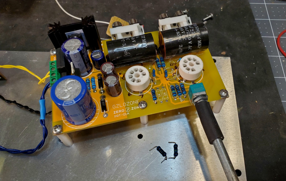
Progress: The mod is now ready for testing. No trace cutting involved, which is nice. This makes everything reversable.
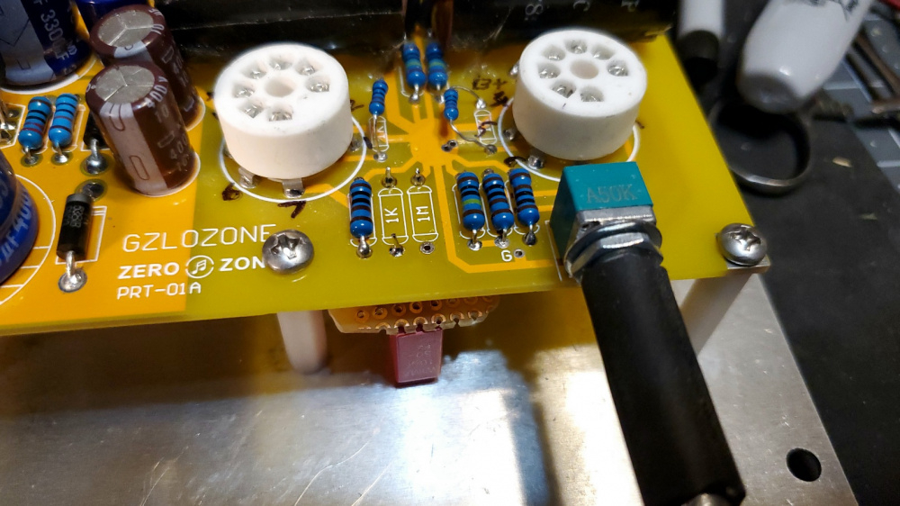
First, I removed the 1k and 1meg resistor from one channel, then cleaned the pads and holes:
Then I inserted the perfboard leads into the bottom side of the board, not unlike pressing an op amp into a socket, so to speak. I kept the leads as short as possible to reduce noise pickup. The longer red lead is the feedback loop going to the RCA output jack.
Then I soldered the perfboard into position from the top side of the PCB. The PCB's plated through holes made this task very easy.
Mod done and ready for testing. The perfboard is tucked away neatly under the PCB:
I like that your feedback jumper wire pretty much crosses perpendicular over the pcb traces. Shouldn't have any noise issues with that at all.
I don't know what temperature you set your soldering station at , what tip size you're using, or how long you dwell but several of your pcb solder joints look like they didn't flow out very well (round ball of solder instead of a nice small fillet). They don't look like "cold" solder joints so I doubt they will be a long term issue. These cheap pcbs from china are probably not plated through holes, just a pad so that makes it a bit trickier. Just a casual observation.
The holes appeared through-plated when I soldered mine. Though I did have some difficulty getting them to wet all the way through to the top even when holding the iron on for a little extra time, so I'd add more solder. Sometimes that would get it to wet all the way through. Sometimes it wouldn't and just blob. I touched up the top side where I had issues. I run silver solder at 650f on my digital Weller. Not hot enough? Just running whatever the original tip was since it works well for me. Seems like a fine tip chisel with high angle flats on both sides running down to a slightly blunt end.
Ya, as Drew mentioned, the PCB holes are through-plated. It is a very high quality board that can take the heat without lifting or damaging traces. I used a temperature controlled Weller WE1010 station with small chisel tip. 720F to 750F for all joints. Solder: Radio Shack 60/40 rosin-core .032 diameter for the entire board. Ya, I probably need to go back and re-flow a few joints here and there. I double checked each joint as I went along and I'm pretty sure that I was getting a good flow through to the top side of the board. But now that you mention it, I see a few spots that look a little blobby. I thought I gave these adequate dwell, but maybe I pulled away too fast.
I do have a bottle of MG chemicals 835 liquid rosin flux and a special bottle/needle to apply small drops to a solder joint. But I did not use it on this project because I was in a hurry to get it soldered up quickly and test it out.
I've been listening to and measuring the mod and stock channels for a while now and am ready to report my findings. Comparisons will be: 1) gain, 2) output impedance, 3) oscillation, 4) freq. resp., 5) distortion profile, 6) RTA spectrum, 7) subjective sound quality. So here goes.
GAIN:
]--------
Stock channel: 14dB @ 1kHz into 10k ohm load.
Mod channel: 6.5dB @ 1kHz into 10k ohm load.
]----------
Stock channel: 18dB @ 1kHz into 22k ohm load.
Mod channel: 8.5dB @ 1kHz into 22k ohm load.
]-----------
Stock channel: 24dB @ 1kHz into 1meg ohm load.
Mod channel: 10.7dB @ 1kHz into 1meg ohm load.
As you can see, the gain is very load dependent. This is due to the high output impedance of this preamp. The mod channel, however, has a lower output impedance and the gain is therefore less affected by changes in load.
OUTPUT IMPEDANCE:
You can calculate the output impedance from the above data using some simple formulas found on-line:
]-------
Stock channel: 20,842 ohms at 1kHz
Mod channel: 6360 ohms at 1kHz
I ran frequency response tests at very high frequencies (100kHz+) with my scope on both the mod and stock channels and could find no signs of oscillation. Square waves at 10kHz have no ringing or overshoot.
FREQUENCY RESPONSE:
I ran FR plots in REW comparing mod and stock channels. Both are ruler flat except for a slight roll off at 20kHz. The mod channel is down about 0.1dB at 20kHz and the stock channel is down about 0.3dB at 20kHz when driving into a 22k ohm load with 100pF of interconnect cable capacitance. If I boost the cable capacitance to about 300pF, the stock channel rolls off by about .8dB at 20kHz and the mod channel is down by about 0.3dB. Again, this is due to the lower output impedance of the mod channel.
I ran distortion profile plots in REW comparing the mod and stock channels. To make the comparison valid, I equalized the input and output RMS voltages applied for the test. This is necessary, because the mod channel has substantially less gain. For both channels, the input voltage was 0.43vac rms and the output voltage was equalized to 1.05vac rms. Both channels were driving into a 22k ohm load with approx 100pF of interconnect cable capacitance. As you can see, almost all distortion is 2nd order. The mod channel is slightly improved at about 0.11% compared to the stock channel at about 0.205%.
I ran RTA spectrum plots in REW comparing the mod and stock channels. Again, I equalized the gain levels at 0.43vac rms in and 1.05vac rms out @ 1kHz to make the comparison valid. Otherwise the noise and distortion levels will be overstated for the higher gain stock channel. In addition, I disconnected my input and output DMM's from the loopback and used very short, properly terminated RCA interconnects to complete the loopback. This is important, because you want to measure the noise and distortion of the DUT alone and it is very easy to mess up this test with unshielded DMM breakout jacks. As you can see, the noise level and distortion is slightly improved for the mod channel.
SOUND QUALITY: So how does it sound? Strangely, the stock version was the clear winner. I listened in mono to one channel at a time, equalizing the gain and swapping cables back and forth. I used the tubes that came with the kit for all listening. The stock version was simply more musical to my ears with a greater sense of depth and dynamic range. The mod channel seemed muffled, compressed and slightly dull by direct comparison. Confirmation bias? Not sure. But the difference in sound quality was very clear to me. Now, maybe my ears simply like the nice, warm sound of 2nd harmonic distortion, but I don't think that this was the cause. And I doubt that I can actually hear a difference between 0.11% 2nd HD and 0.205% 2nd HD. Was the difference due to the fact that the mod channel adds a coupling cap at the input? Don't know. All I know is that the stock channel is DC connected at the input and just sounds cleaner, crisper, and more dynamic. I tried to crank the volume up on the mod channel to get it to sound more like the stock channel, but I couldn't. It just did not seem to have the same level of dynamic "punch" that I could get out of the stock channel.
Interesting outcome. I would think any confirmation bias would favor the Mod version, especially since you knew THD was lower and bandwidth was flatter. Could this be an example of how we still can't measure everything our ears prefer?
Comments
Significantly. I should also mention a measurement error on my part. The 23dB gain measurement that I reported above is somewhat overstated because it was taken with the preamp driving into its internal 1 meg load resistor. I forgot to add a resistor in my test setup to simulate having the preamp drive into the input impedance of a typical power amp. When I do this, the gain drops from 23db down to 18dB @ 1kHz when driving into a 22k ohm load. And it drops further to about 14dB @ 1kHz when driving into a 10k ohm load. The reason for the huge drop in gain with changes in load is due to the high output impedance of this preamp.
This is very simple single stage tube preamp. No feedback is used. It has a plate resistor, cathode resistor with no bypass, and a grid resistor. Input goes through a 50k pot. Output goes through a 2.2uF (I used 5uF) 400V cap and drives into a 1 meg resistor at the output. That is it.
You certainly can drive the gain way down (to unity gain actually) with tons of negative feedback but then it loses its signature tube sound.
I like a little negative feedback in a tube power amp where there are non-linearities due to the output transformer.
Agreed. We want to keep some of that "glorious" 2nd harmonic distortion to warm up the soundstage. So far, I am really beginning to like this "no feedback" sound quality. Something about it is very pleasing to the ear. And with just a small amount of feedback, a gain of about 8 to 10dB should be possible. Right now I am setting up the cables to perform loopback harmonic distortion and RTA spectrum tests with REW. This should give me a better idea as to what the actual harmonic distortion profile looks like. I'm also setting up LTspice to model the circuit and try out various feedback resistor values. I'll post some graphs as I go along.
There you go! Sounds like a good plan.
When it's running steady state (no input signal) what is the voltage drop across the cathode resistor?
A: 2.72vdc drop across the 1k ohm cathode resistor. So the idle current for the stock circuit would be 2.7ma.
Hmmm? I wonder how much better or how much worse the proper voltage drop LED (or two) might sound as a replacement for that 1k cathode resistor. I tried that with one preamp circuit I built and it was noticably better. I think I had to use two green LED's in series to hit my target voltage drop.
Sorry, just another rabbit hole to dive into")
I'll add LED testing to my list of future mods.")
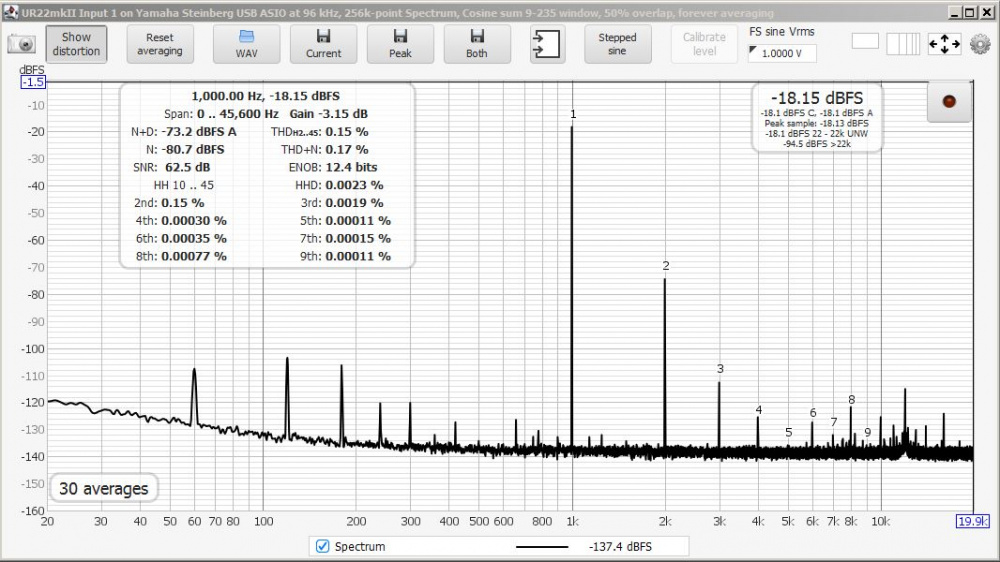
I ran a few calibrated loopback RTA spectrum and HD profile plots late last night. They look very good, much better than I expected. For the RTA spectrum test, I fed the 6J1 preamp's RCA inputs with a 139.5mv RMS 1kHz sine wave. This produced 897.7mv RMS @ 1kHz at the 6J1 preamp's RCA outputs (a gain of 16dB). This is a fairly high level signal, enough to drive a typical power amp to a very loud listening level. The load on the preamp's outputs was 20k ohm plus the RCA interconnect cable's capacitance of 272pF. Looks pretty good to me. You can see a little bump at 60Hz, 120Hz, etc., but not too bad at all.
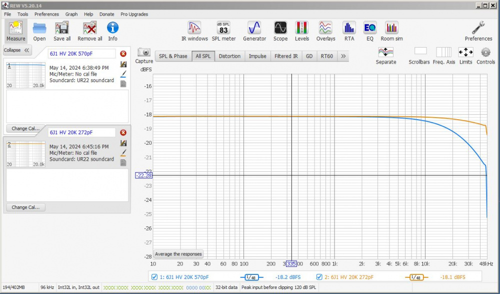
For the frequency response and harmonic distortion profile tests, the RMS input and output voltages were the same as above, but instead of measuring a single 1kHz tone, I send the preamp REW's swept test tone from 10Hz to 48kHz. For comparison purposes, I also tested the frequency response driving into 20k ohm plus a much higher cable capacitance of 570pF. Ruler flat down to 10Hz on the low end. On the high end, the 20k/272pF load plot is down about 0.3dB at 20kHz. The 20K/570pF load plot, however, is down about 1.2dB at 20kHz. This clearly shows how interconnect cable capacitance can influence high frequency response when using a preamp with a very high output impedance. Craig's unity gain cathode follower preamp, for instance, has a very low output impedance and would not suffer from this type of cable capacitance roll off.
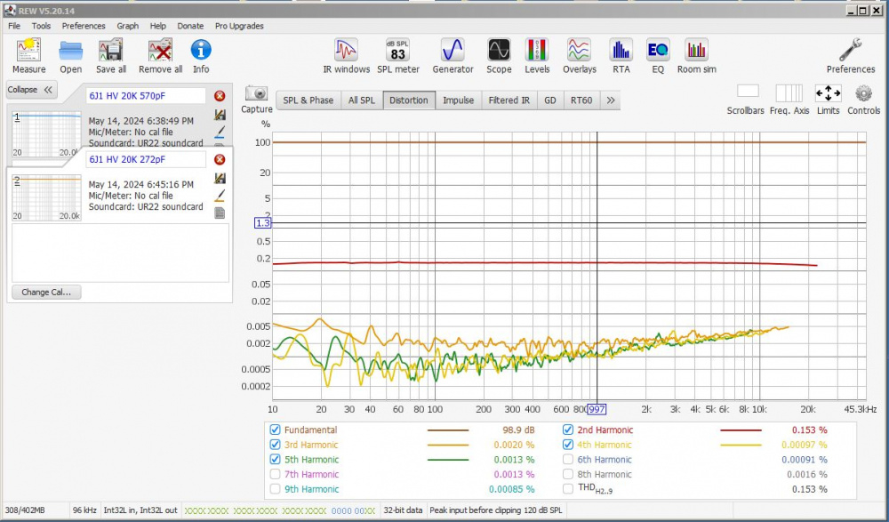
Finally, here is the harmonic distortion profile plot. HD is almost all 2nd order at about 0.15% This is much better than the other 6J1 preamp, which measured in the 0.5 to 1.0% 2nd HD range when outputing roughly the same rms voltage levels. And this is without feedback!
Oh, forgot to mention, I used the tubes that came with the kit for the above measurements. Have not had a chance to test other tubes yet. I would imagine that different tubes will shift the HD and FR figures around a little bit. I'll have to do some "measurement rolling" to see what happens!")
Was thinking some day I might take a stab at one of the basic early Pass Zen amp versions (Oah the simplicity, my kriptonite!). They seem to have low gain. This preamp could work out for it as a first stage. But some of the versions have higher input capacitance apparently.
I built the Tortello Headphone amp many years ago. This is a Nelson Pass inspired headphone amplifier that uses a single JFET (Hexfet?) gain stage to drive a pair of headphones. I'll hook it up to this preamp and see how badly the high frequencies roll off. It should be fairly easy to include both the headphone amp and 6J1 preamp inside the REW loopback measurement chain and then run a combined frequency response curve.
https://www.diyaudio.com/community/threads/zen-like-headphones-amp.2451/
I tested the 6J1 preamp driving into the input of my Tortello headphone amp. The Hexfet (IRF610) at the input did not cause a roll off of high frequencies, but it did cause a huge increase in 2nd harmonic distortion at very high frequencies. See below:
HD profile of the Tortello amp alone. Note that 2nd HD is rising with frequency but tops out at about 0.3% at 20kHz.
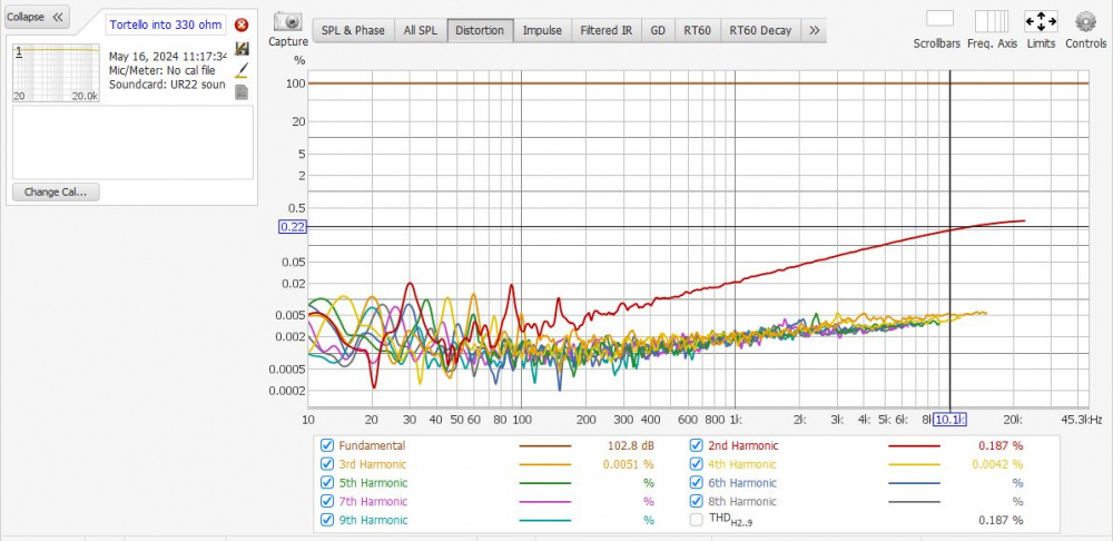
HD profile of the 6J1 preamp AND Tortello amp in the measurement loop. Note that 2nd HD now tops out at almost 2% at 20kHz. The input resistor to ground on the Tortello amp is 20K ohms. But something about the Hexfet downstream is driving the distortion way up at high frequencies.
Based on LTspice modeling, I made a little perfboard to:
1) reduce the gain from approx 16dB to 8dB
2) add a little feedback to lower distortion
3) add a coupling cap at the input to block DC
The little perfboard will sit underneath the stock PCB and be connected with very short leads. Plan is to simply remove 2 resistors from the stock PCB and then solder the four leads from the perfboard to the vacated holes and output RCA lug. Plan is also to mod one channel at a time, leaving the other channel stock. This way I can listen to music and make measurements while I switch back and forth between modified and unmodified channels.
Do not know if this will work, as my LTspice modding experience is somewhat limited. It tests good in the model. Hopefully it will not go into oscillation or sound bad.
Good plan Bill.
Progress: The mod is now ready for testing. No trace cutting involved, which is nice. This makes everything reversable.
First, I removed the 1k and 1meg resistor from one channel, then cleaned the pads and holes:
Then I inserted the perfboard leads into the bottom side of the board, not unlike pressing an op amp into a socket, so to speak. I kept the leads as short as possible to reduce noise pickup. The longer red lead is the feedback loop going to the RCA output jack.
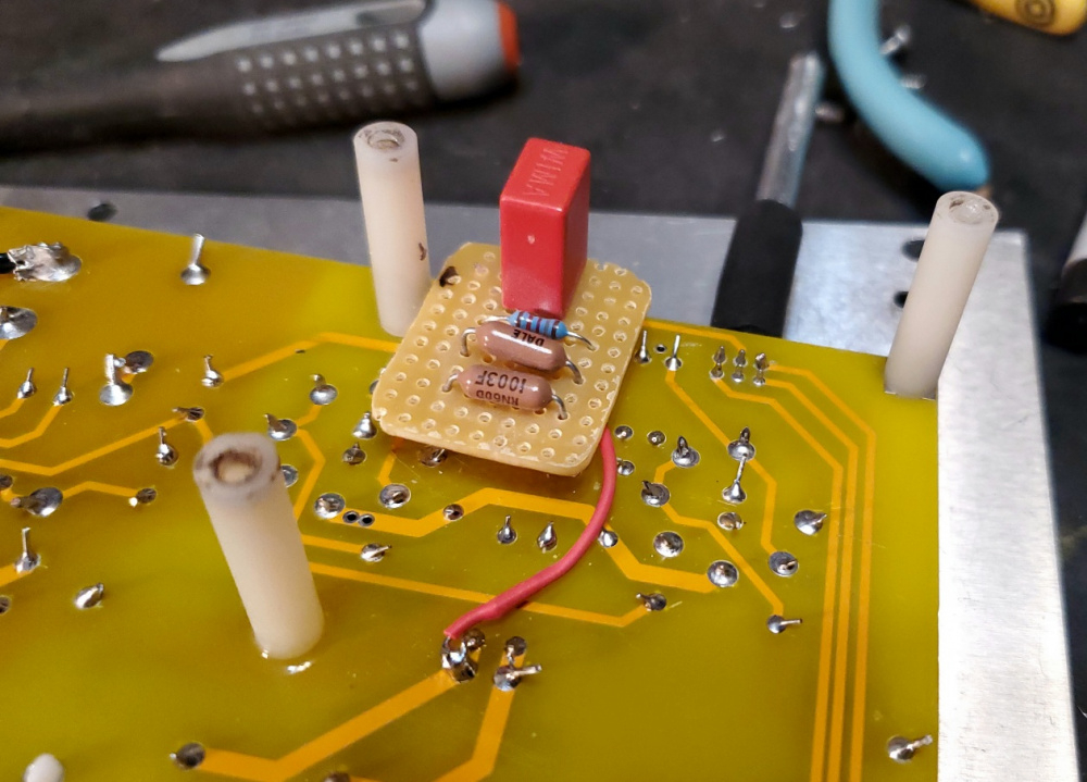
Then I soldered the perfboard into position from the top side of the PCB. The PCB's plated through holes made this task very easy.
Mod done and ready for testing. The perfboard is tucked away neatly under the PCB:
I like that your feedback jumper wire pretty much crosses perpendicular over the pcb traces. Shouldn't have any noise issues with that at all.
I don't know what temperature you set your soldering station at , what tip size you're using, or how long you dwell but several of your pcb solder joints look like they didn't flow out very well (round ball of solder instead of a nice small fillet). They don't look like "cold" solder joints so I doubt they will be a long term issue. These cheap pcbs from china are probably not plated through holes, just a pad so that makes it a bit trickier. Just a casual observation.
Oah solder shaming, are we?
The holes appeared through-plated when I soldered mine. Though I did have some difficulty getting them to wet all the way through to the top even when holding the iron on for a little extra time, so I'd add more solder. Sometimes that would get it to wet all the way through. Sometimes it wouldn't and just blob. I touched up the top side where I had issues. I run silver solder at 650f on my digital Weller. Not hot enough? Just running whatever the original tip was since it works well for me. Seems like a fine tip chisel with high angle flats on both sides running down to a slightly blunt end.
Ya, as Drew mentioned, the PCB holes are through-plated. It is a very high quality board that can take the heat without lifting or damaging traces. I used a temperature controlled Weller WE1010 station with small chisel tip. 720F to 750F for all joints. Solder: Radio Shack 60/40 rosin-core .032 diameter for the entire board. Ya, I probably need to go back and re-flow a few joints here and there. I double checked each joint as I went along and I'm pretty sure that I was getting a good flow through to the top side of the board. But now that you mention it, I see a few spots that look a little blobby. I thought I gave these adequate dwell, but maybe I pulled away too fast.
Get some paste flux and liquid flux. Clean with 99%isopropyl alcohol, even if it says it's no clean flux. Life will be so much easier.
I do have a bottle of MG chemicals 835 liquid rosin flux and a special bottle/needle to apply small drops to a solder joint. But I did not use it on this project because I was in a hurry to get it soldered up quickly and test it out.
I've been listening to and measuring the mod and stock channels for a while now and am ready to report my findings. Comparisons will be: 1) gain, 2) output impedance, 3) oscillation, 4) freq. resp., 5) distortion profile, 6) RTA spectrum, 7) subjective sound quality. So here goes.
GAIN:
]--------
Stock channel: 14dB @ 1kHz into 10k ohm load.
Mod channel: 6.5dB @ 1kHz into 10k ohm load.
]----------
Stock channel: 18dB @ 1kHz into 22k ohm load.
Mod channel: 8.5dB @ 1kHz into 22k ohm load.
]-----------
Stock channel: 24dB @ 1kHz into 1meg ohm load.
Mod channel: 10.7dB @ 1kHz into 1meg ohm load.
As you can see, the gain is very load dependent. This is due to the high output impedance of this preamp. The mod channel, however, has a lower output impedance and the gain is therefore less affected by changes in load.
OUTPUT IMPEDANCE:
You can calculate the output impedance from the above data using some simple formulas found on-line:
]-------
Stock channel: 20,842 ohms at 1kHz
Mod channel: 6360 ohms at 1kHz
I'll continue this on the next post . . .
OSCILLATION:
I ran frequency response tests at very high frequencies (100kHz+) with my scope on both the mod and stock channels and could find no signs of oscillation. Square waves at 10kHz have no ringing or overshoot.
FREQUENCY RESPONSE:
I ran FR plots in REW comparing mod and stock channels. Both are ruler flat except for a slight roll off at 20kHz. The mod channel is down about 0.1dB at 20kHz and the stock channel is down about 0.3dB at 20kHz when driving into a 22k ohm load with 100pF of interconnect cable capacitance. If I boost the cable capacitance to about 300pF, the stock channel rolls off by about .8dB at 20kHz and the mod channel is down by about 0.3dB. Again, this is due to the lower output impedance of the mod channel.
continued next post . . .
DISTORTION PROFILE:
I ran distortion profile plots in REW comparing the mod and stock channels. To make the comparison valid, I equalized the input and output RMS voltages applied for the test. This is necessary, because the mod channel has substantially less gain. For both channels, the input voltage was 0.43vac rms and the output voltage was equalized to 1.05vac rms. Both channels were driving into a 22k ohm load with approx 100pF of interconnect cable capacitance. As you can see, almost all distortion is 2nd order. The mod channel is slightly improved at about 0.11% compared to the stock channel at about 0.205%.
RTA SPECTRUM:
I ran RTA spectrum plots in REW comparing the mod and stock channels. Again, I equalized the gain levels at 0.43vac rms in and 1.05vac rms out @ 1kHz to make the comparison valid. Otherwise the noise and distortion levels will be overstated for the higher gain stock channel. In addition, I disconnected my input and output DMM's from the loopback and used very short, properly terminated RCA interconnects to complete the loopback. This is important, because you want to measure the noise and distortion of the DUT alone and it is very easy to mess up this test with unshielded DMM breakout jacks. As you can see, the noise level and distortion is slightly improved for the mod channel.
SOUND QUALITY: So how does it sound? Strangely, the stock version was the clear winner. I listened in mono to one channel at a time, equalizing the gain and swapping cables back and forth. I used the tubes that came with the kit for all listening. The stock version was simply more musical to my ears with a greater sense of depth and dynamic range. The mod channel seemed muffled, compressed and slightly dull by direct comparison. Confirmation bias? Not sure. But the difference in sound quality was very clear to me. Now, maybe my ears simply like the nice, warm sound of 2nd harmonic distortion, but I don't think that this was the cause. And I doubt that I can actually hear a difference between 0.11% 2nd HD and 0.205% 2nd HD. Was the difference due to the fact that the mod channel adds a coupling cap at the input? Don't know. All I know is that the stock channel is DC connected at the input and just sounds cleaner, crisper, and more dynamic. I tried to crank the volume up on the mod channel to get it to sound more like the stock channel, but I couldn't. It just did not seem to have the same level of dynamic "punch" that I could get out of the stock channel.
Try bypassing the input cap with a jumper.
Interesting outcome. I would think any confirmation bias would favor the Mod version, especially since you knew THD was lower and bandwidth was flatter. Could this be an example of how we still can't measure everything our ears prefer?
Exactly what I was thinking.