Will have to ask the OP, @Tom_S , if he thinks we are hijacking. I didn't think so, as this is also a cheap, simple tube linestage. I think the sonic comparison of basically the same kit, but at a higher voltage, seems closely related to me. What you think, Tom? Move to a new thread?
@DrewsBrews said:
Yep I noticed one of the standoffs in a previous pic. Good idea!
As another datapoint.. On my junky dmm I get 6.9v, and 5.2v across the filter caps before and after the LM7806. So pretty close to yours, just consistently lower so probably meter variance. If there is anything not right, it is likely the way these parts were manufactured (IE cheap knockoff) which would not be surprising.
I do get 6.3vac right off the transformer while it is still hooked up to the circuit. Which should be 8.8v peak.
@DrewsBrews , @ani_101 , I'm going to be placing a Mouser order for some other stuff by the end of next week. If you want, I could order a few extra of the below 7806 chips and mail each of you a couple of the regulators when they come in. Spec sheet says they have a minimum input of 8 volts, so they should work. If not, we will just have to be satisfied with running our tubes at about 5.2 to 5.4 volts.
that will be great Bill. once yu have this figured out, i'll put it together. if you can please detail out the checks / measurmenets we need to do to ensure it's been put together properly.
Up to you if you want to go through the trouble of shipping stuff out.. wonder if they would survive stamp mail if you bring it to the post office and request manual/hand "canceling" so it doesn't go through the machine. Though I hear they tend to resist that anymore so they might go through the machine anyway.
While I am waiting for new LM7806 regulator chips from Mouser, I decided to keep going and finish the cabinet part of the build.
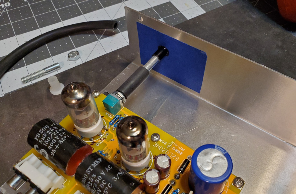
I used a one inch section of 7/32" ID vacuum hose to connect the volume pot to a 1/4" diameter by 2.5" long extension shaft. I cut the extension shaft from a 4" long 1/4-20 bolt. The vacuum hose grips the 1/4" bolt and knurled pot tightly on both ends. No slippage without glue. I epoxied a 9/32" ID nylon bushing to the front panel to receive the bolt and act as a bearing. Operation is very smooth with no wobble.
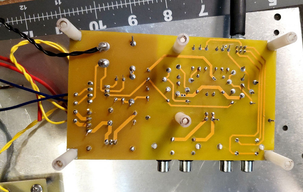
To align and drill the six 6-32 screws for the standoffs, I placed a small dot of mortite caulking in the approximate spot of each standoff, then placed a small square of wax paper backing on top of each dot of mortite. Then I slowly lowered and positioned the PCB to its final resting place, pushing the PCB down firmly into the wax paper and mortite. This left an impression of each standoff on the wax paper that I could use to drill precisely positioned pilot holes. Worked great! Almost a perfect fit. One of the six screw holes was just a little off, but I was able to widen the hole just a tad to get a good fit to all six holes. Volume control shaft is aligned perfectly with the bushing.
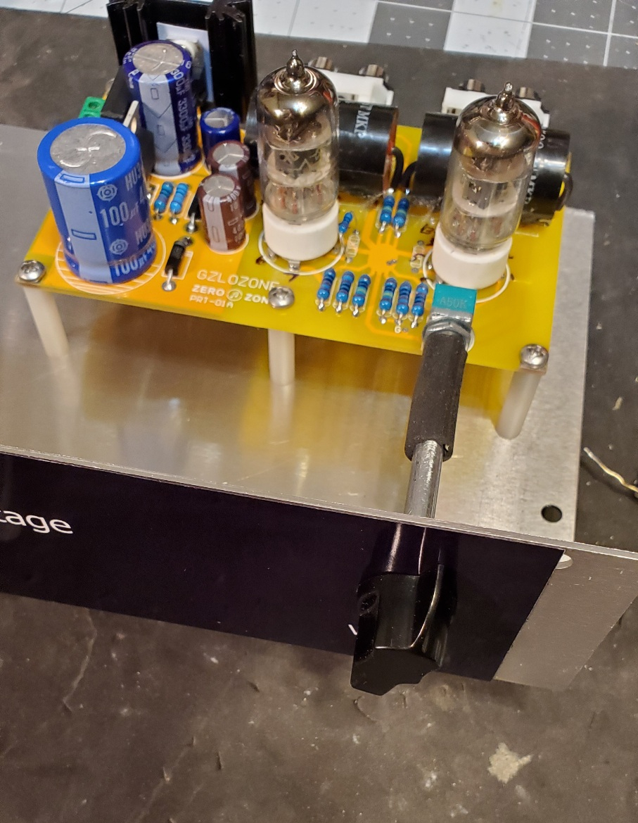
I'm using old skool "Chicken head" knobs to give it a classic vintage guitar amp look. Some do not like the look of chicken head knobs, but I think they look cool. I am also using a classic rotary type on/off switch that I salvaged from a vintage amp.
@4thtry said:
I used a one inch section of 7/32" ID vacuum hose to connect the volume pot to a 1/4" diameter by 2.5" long extension shaft. I cut the extension shaft from a 4" long 1/4-20 bolt. The vacuum hose grips the 1/4" bolt and knurled pot tightly on both ends. No slippage without glue.
@4thtry said:
To align and drill the six 6-32 screws for the standoffs, I placed a small dot of mortite caulking in the approximate spot of each standoff, then placed a small square of wax paper backing on top of each dot of mortite. Then I slowly lowered and positioned the PCB to its final resting place, pushing the PCB down firmly into the wax paper and mortite. This left an impression of each standoff on the wax paper that I could use to drill precisely positioned pilot holes.
Thanks for posting Bill. This if fun to follow. Pretty clever tricks.
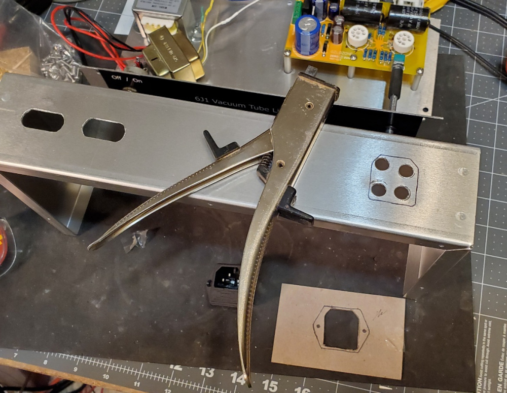
Rear panel progress: Drilled slots to access the in & out RCA jacks. Then made a template for the large IEC power inlet/fuse holder. Cutting out these odd rectangles is always a big pain. This is how I did it:
After marking the cutout, I drilled four holes that were large enough to start the nibbler tool:
I nibbled out the center, careful to leave the guidelines visible so that I could very accurately widen the rectangular hole to the guidelines using a file :
First, I placed a small dab of mortite caulking onto the top panel directly above each tube. To prevent sticking, I pressed a small piece of clear plastic (from a sandwich bag) onto each dab of caulking:
Then, I slowly lowered the top cover onto the tubes, careful to keep it in perfect alignment as I lowered the top cover and pressed the tubes into the soft mortite:
After removing the cover, I could clearly see the impression left by each tube:
I then drilled a small 1/8" pilot hole in the center of each tube's impression:
Then increased both holes to 7/8" diameter:
I could only raise the PCB a total of 1" using standoffs because I needed to keep the volume control knob near the center of the front panel. So, the tubes only stick out the top panel about 1/2". The glow of the filament, however, is still visible at this relatively low height.
If I install 3/4" high tube socket savers, then the tubes will be 1-1/4" proud of the top panel and it will look like the picture below (I don't have socket savers yet, I used small 3/4" blocks of wood to raise the tubes for the photo). I think this probably looks better, but the lower profile would provide better EMI and RF shielding of the tube elements. Which one would you go with? By the way, I plan to add walnut side panels that partially wrap around the front panel and cover up the exposed aluminum. Should look pretty cool when I get it all buttoned up.
@DrewsBrews said:
I could spare a top mount transformer cover and 50kohm aliexpress "alps" pot if you want it.
Thanks for the offer, Drew. The alps pot would certainly be better in terms of audio quality, I know. But the cheap little PCB mount pot is not too bad in terms of noise or intermittant wiper action. It keeps the signal path very short, so if I replaced it with an alps, the preamp would probably pick up more noise from the extra wiring. Also, I already have the space marked out for the xformer (s) and am beginning to drill and and wire up the remaining parts. Should have everything buttoned up and ready for REW FR and distortion testing in a few days. I'm also roughing out the circuits and loading the data into LTspice to see if I can "improve" upon this simple circuit. Thanks again.
@DrewsBrews said:
Up to you if you want to go through the trouble of shipping stuff out.. wonder if they would survive stamp mail if you bring it to the post office and request manual/hand "canceling" so it doesn't go through the machine. Though I hear they tend to resist that anymore so they might go through the machine anyway.
Drew & Ani, I got the new LM7806 regulator chips from Mouser and tested one of them in the preamp. I get pretty much the same voltages as before, so the original LM7806 chips are probably OK. The new chip gives me 5.6vdc on the heaters instead of 5.4vdc using the original chip. The voltage between the rectifier and LM7806 is 7.10vdc (was 7.15vdc using the original chip). I think the basic problem is that the 6v transformer winding simply does not create a high enough voltage to bias the chip. Not a big problem, though, as the circuit seems to work OK at 5.4vdc.
On a related note, while I was browsing and ordering from Mouser, I found a small Triad 10VCT transformer rated at 600ma. Very small, PCB mount type. Really cheap. I tested it today and it works great. Gives me 6.0vdc on the heaters with only about 2mv of AC ripple. The heatsink on the 7806 chip gets up to about 120F after about 30 minutes, so I think I will add a 2 ohm 10W dropping resistor in series with the secondary to drop the incoming AC voltage just a tad. This should keep the LM7806 heatsink at about 100F or less. I'll make a little PCB board for the xformer+resistor and then mount it on standoffs next to the other xformer. Here is a link:
I could only raise the PCB a total of 1" using standoffs because I needed to keep the volume control knob near the center of the front panel. So, the tubes only stick out the top panel about 1/2". The glow of the filament, however, is still visible at this relatively low height.
Like the recessed look - a bit different from the usual exposed tube stuff.
And it looks like my Musical Paradise Tube DAC MP-D1 MK3 (currently discontinued) - The tubes barely peek out
@ani_101 said:
Bill, is the 6V of the new transformer significant compared to the 5.4V of the stock? Is this something you recommend we try out and install?
Ani, I did not notice a difference in the hum level using the 6V of the new transformer compared to the 5.4V of the stock. However, I have only played a few music selections at this point. The raw PCB was unshielded, without an enclosure, and not properly grounded. There was a little hum because of this, so I don't think I can make a valid comparison at this time. I need to get the PCB buttoned up in the final enclosure, with all the star grounding wires properly connected. Then I can do a valid a/b listening comparison of the two power supplies by swapping connections back and forth. I also want to run an RTA plot in REW, comparing the noise floor generated by each filament supply. My feeling is that I will be unable to see or hear a difference, but this is only a guess at this point.
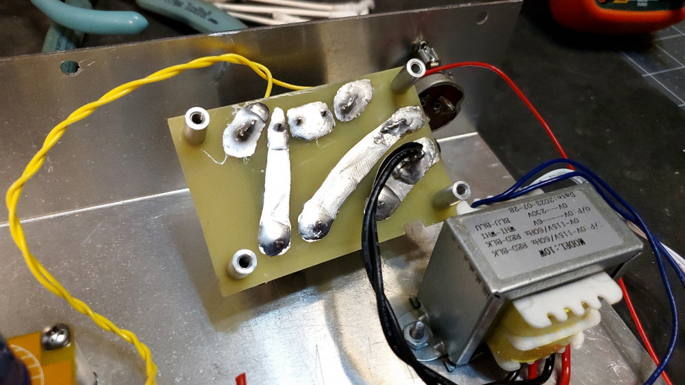
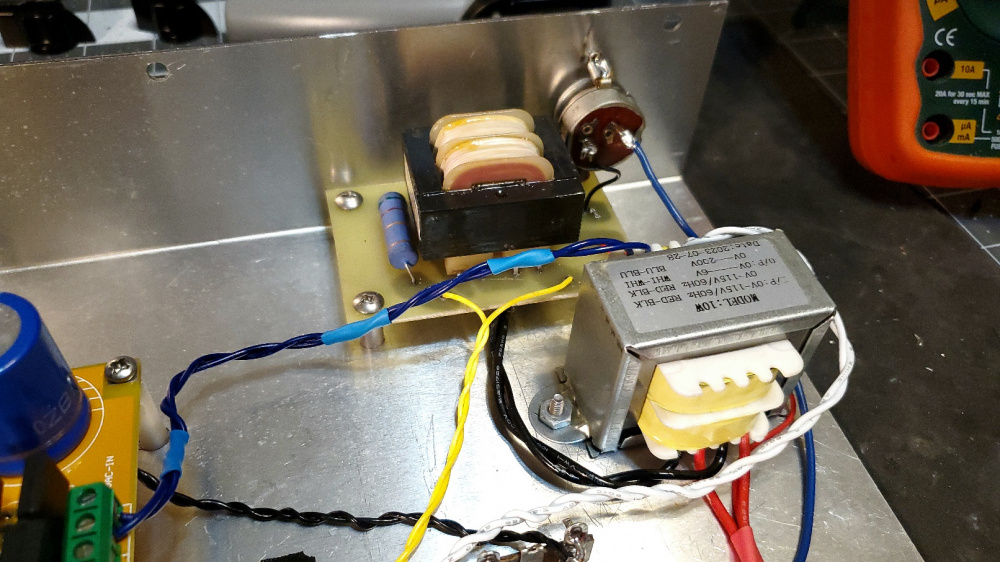
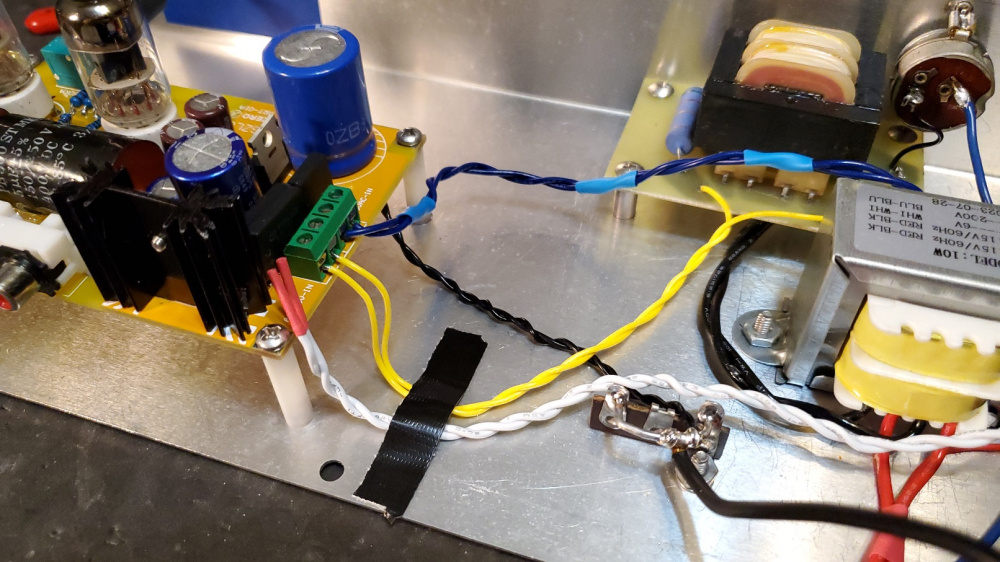
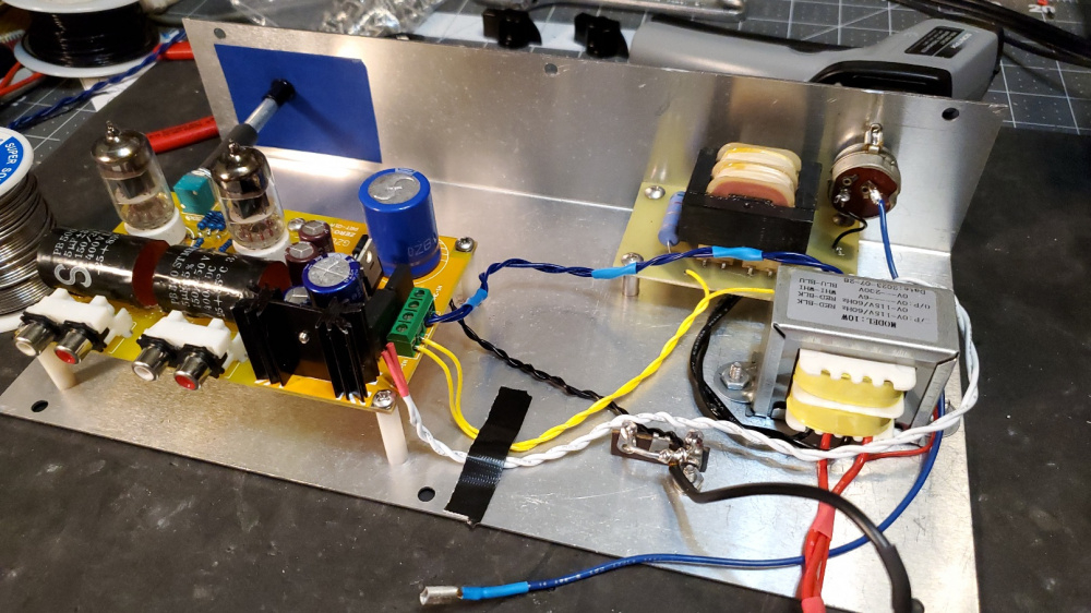
I DIYed a little circuit board for the small Triad 10V transformer so that I could mount it with standoffs. This xformer's secondary measured 11.3vac under full load, so I dropped this to about 9vac with a 5 ohm 5W series resistor (see pic). This then produces about 9vdc after the rectifier and a tightly regulated 6vdc after the LM7806 regulator chip. Heatsink stays at about 101F or so after 30 minutes run time. Resistor gets up to about 106F, which feels hot, but not too hot. Seems to work very good and there is only about 2.5mv of AC ripple (120Hz) riding on the 6vdc.
I have it all wired up and am ready to begin my final measurements and listening tests.
@4thtry said:
To align and drill the six 6-32 screws for the standoffs, I placed a small dot of mortite caulking in the approximate spot of each standoff, then placed a small square of wax paper backing on top of each dot of mortite. Then I slowly lowered and positioned the PCB to its final resting place, pushing the PCB down firmly into the wax paper and mortite. This left an impression of each standoff on the wax paper that I could use to drill precisely positioned pilot holes. Worked great! Almost a perfect fit. One of the six screw holes was just a little off, but I was able to widen the hole just a tad to get a good fit to all six holes. ## Volume control shaft is aligned perfectly with the bushing.
For future reference in aligning the pot shaft to the panel mounted knob, I have used this sort of U-joint in the past and still have a small box of them somewhere in my shop - I'll try to dig them out to see if they are suitable for this application.
Excellent tip! I'll have to add a set of these on my next Amazon order. Looks like the perfect solution. The universal joint would be able to easily make up for small amounts of DIY alignment error. I was probably just plain lucky to get an almost perfect alignment on my first try! The rubber vacuum hose idea will compensate for a little bit of error, but not much. With the universal joint, you could probably turn a 45 degree corner and still be OK.
Bill - let me send you these aluminum things. I have no idea what they were for. Something for Rockwell/Collins. They are aluminum and the hole is about 1". They just need a little polishing.
@Tom_S said:
Bill - let me send you these aluminum things. I have no idea what they were for. Something for Rockwell/Collins. They are aluminum and the hole is about 1". They just need a little polishing.
Thanks for the offer, Tom! Those look really cool, with a nice waveguide type bevel. Wish I could use them, but I am afraid that they may be too large in diameter. The washers I used in the above photo are 1.5" in diameter and, as you can see, the two washers almost hit each other when centered on the tubes. The distance between the two washers is about 0.2" So, the maximun diameter of any ring is therefore 1.5 + (.2/2) = 1.6" Otherwise they will hit each other. The inside diameter of my washers is 0.812" and the outside diameter of the 6J1 tube is 0.70" The hole that I cut in the chassis top is 0.875" and clears the 6J1 tube by 0.175". So if I tried to use your rings, I would probably have to truncate the sides of the rings and then widen my 7/8" chassis hole out to 1".
@ani_101 , I spent a few hours listening to the Ali Express 5.4vdc filament hookup verses the Triad 6vdc filament hookup. (swapping the transformer wires back and forth on the PCB terminals and listening). The hum level is extremely low with both voltage hookups. With the volume control on the 6J1 preamp and my bench Lepai 2020 amp turned all the way up, I can barely hear any hum or hiss from the speakers. I have to put my ear within a few inches of the woofer to hear anything at all. I also played several music selections and could hear no difference between the 5.4v and 6v transformers. Both sounded very good.
Now, I know from experience that when you run a vacuum tube at a lower than specified filament voltage, this reduces the transconductance of the tube. This, in turn, will raise the output impedance at the plate of the tube, all else in the circuit being equal. The tube therefore will roll off the high frequencies a little bit sooner when driving into the same interconnect cable capacitance and power amp input impedance load. So, I tested and compared the frequency response of the 5.4v and 6v transformers to see if this made a difference. It did not. On my scope, both hookups are ruler flat out to 10kHz and only down about 0.1dB at 20kHz. The -3dB point is about 120kHz. So, in answer to your question, there is no need to use the Triad 10V transformer to boost the filaments to 6vdc. The original xformer should work just fine at 5.4vdc.
I tested this preamp's gain at 1kHz. With 146mv RMS at the input (yellow trace), it produces 2.27v RMS at the output (blue trace). This is a gain of 15.54 times or 23.83dB! Wow! This is alot of gain. If distortion is high, this preamp might be a candidate for installing a feedback mod. The other 6J1 preamp only had about 18dB of gain in stock form. And we reduced this down to about 6 to 8dB using negative feedback and other mods.
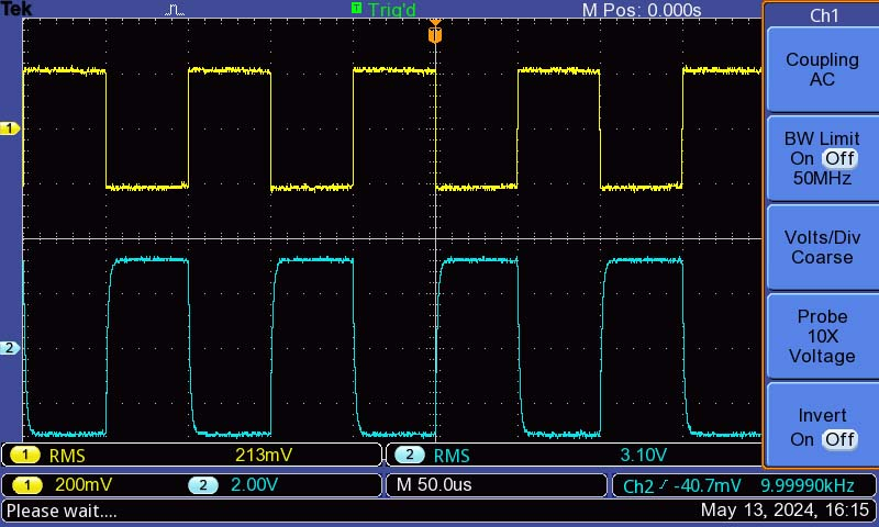
I also did a 10kHz square wave test. Here is what the input verses the output looks like. No ringing. The slight rounding is due to the -3dB roll off at 100kHz.
That much gain makes it unusable. I built my tube preamp as a cathode follower so it actaully has a gain of -0.92 dB. None of my power amps need a preamp with gain.
Comments
Will have to ask the OP, @Tom_S , if he thinks we are hijacking. I didn't think so, as this is also a cheap, simple tube linestage. I think the sonic comparison of basically the same kit, but at a higher voltage, seems closely related to me. What you think, Tom? Move to a new thread?
@DrewsBrews , @ani_101 , I'm going to be placing a Mouser order for some other stuff by the end of next week. If you want, I could order a few extra of the below 7806 chips and mail each of you a couple of the regulators when they come in. Spec sheet says they have a minimum input of 8 volts, so they should work. If not, we will just have to be satisfied with running our tubes at about 5.2 to 5.4 volts.
https://www.mouser.com/ProductDetail/Nisshinbo/NJM7806FA?qs=O60Zvfi0BOMmsIH7bxZshw==
that will be great Bill. once yu have this figured out, i'll put it together. if you can please detail out the checks / measurmenets we need to do to ensure it's been put together properly.
"Will have to ask the OP, @Tom_S , if he thinks we are hijacking. "
Makes no difference to me. No need to start another thread. It's still using the same tube and is an inexpensive kit.
Up to you if you want to go through the trouble of shipping stuff out.. wonder if they would survive stamp mail if you bring it to the post office and request manual/hand "canceling" so it doesn't go through the machine. Though I hear they tend to resist that anymore so they might go through the machine anyway.
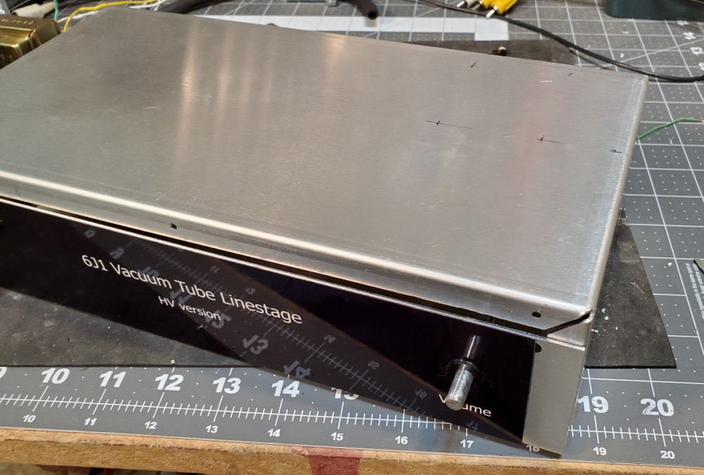
While I am waiting for new LM7806 regulator chips from Mouser, I decided to keep going and finish the cabinet part of the build.
I used a one inch section of 7/32" ID vacuum hose to connect the volume pot to a 1/4" diameter by 2.5" long extension shaft. I cut the extension shaft from a 4" long 1/4-20 bolt. The vacuum hose grips the 1/4" bolt and knurled pot tightly on both ends. No slippage without glue. I epoxied a 9/32" ID nylon bushing to the front panel to receive the bolt and act as a bearing. Operation is very smooth with no wobble.
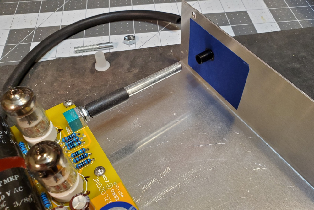
To align and drill the six 6-32 screws for the standoffs, I placed a small dot of mortite caulking in the approximate spot of each standoff, then placed a small square of wax paper backing on top of each dot of mortite. Then I slowly lowered and positioned the PCB to its final resting place, pushing the PCB down firmly into the wax paper and mortite. This left an impression of each standoff on the wax paper that I could use to drill precisely positioned pilot holes. Worked great! Almost a perfect fit. One of the six screw holes was just a little off, but I was able to widen the hole just a tad to get a good fit to all six holes. Volume control shaft is aligned perfectly with the bushing.
I'm using old skool "Chicken head" knobs to give it a classic vintage guitar amp look. Some do not like the look of chicken head knobs, but I think they look cool. I am also using a classic rotary type on/off switch that I salvaged from a vintage amp.
Thanks for posting Bill. This if fun to follow. Pretty clever tricks.
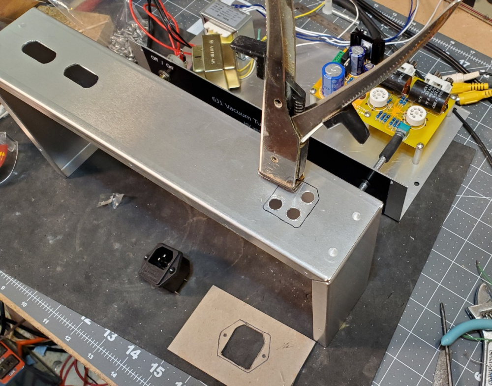
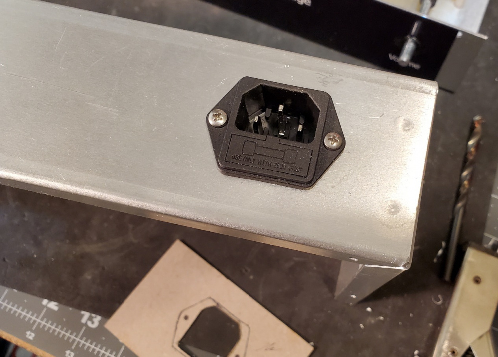
Rear panel progress: Drilled slots to access the in & out RCA jacks. Then made a template for the large IEC power inlet/fuse holder. Cutting out these odd rectangles is always a big pain. This is how I did it:
After marking the cutout, I drilled four holes that were large enough to start the nibbler tool:
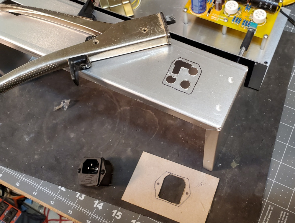
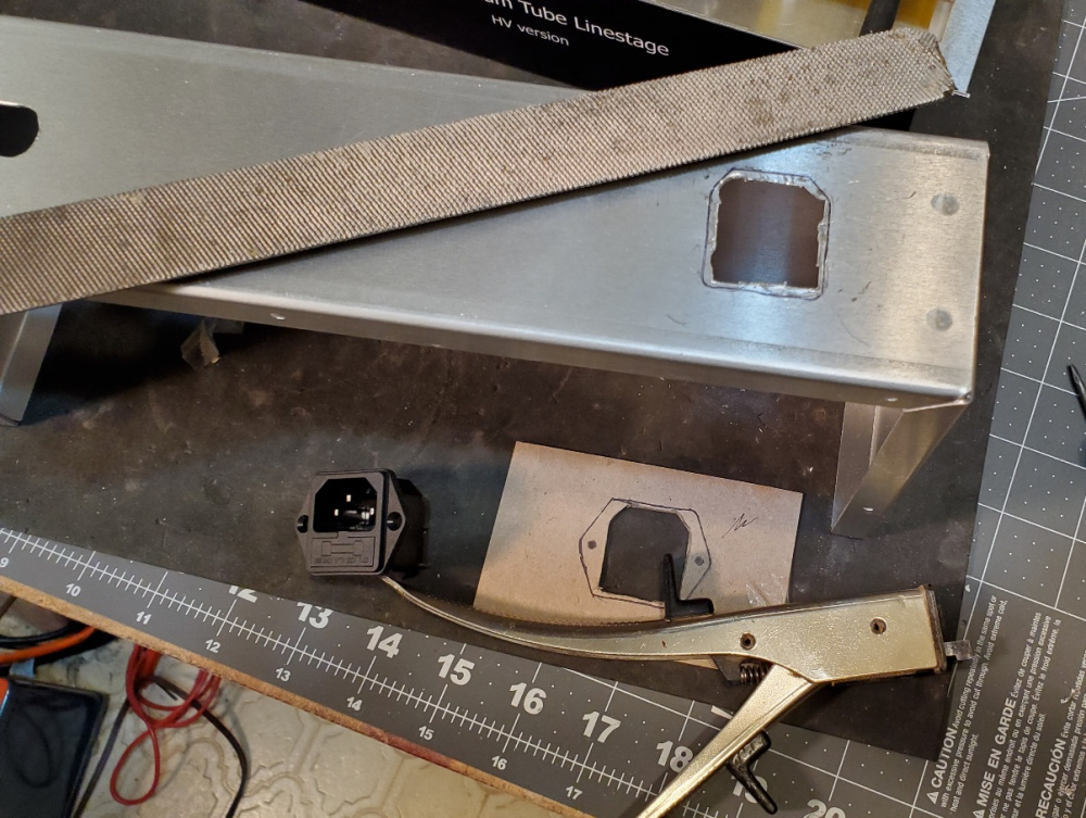
I nibbled out the center, careful to leave the guidelines visible so that I could very accurately widen the rectangular hole to the guidelines using a file :
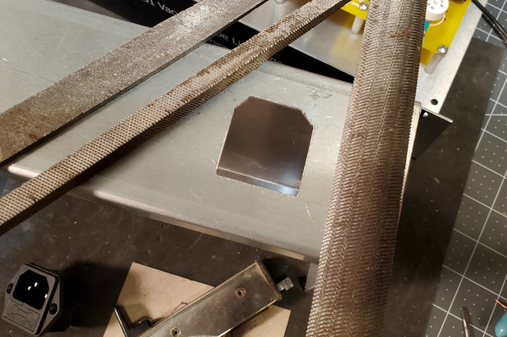
Finished. A perfect fit:
Cutting the tube holes:
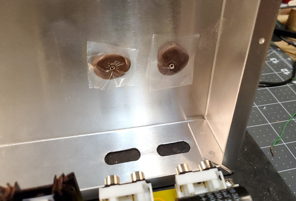
First, I placed a small dab of mortite caulking onto the top panel directly above each tube. To prevent sticking, I pressed a small piece of clear plastic (from a sandwich bag) onto each dab of caulking:
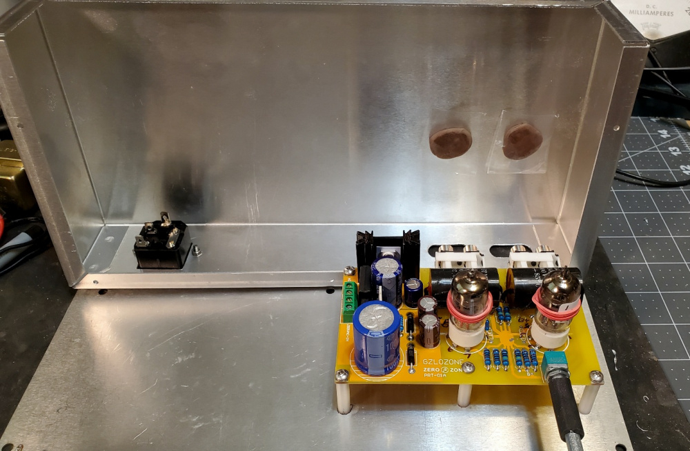
Then, I slowly lowered the top cover onto the tubes, careful to keep it in perfect alignment as I lowered the top cover and pressed the tubes into the soft mortite:
After removing the cover, I could clearly see the impression left by each tube:
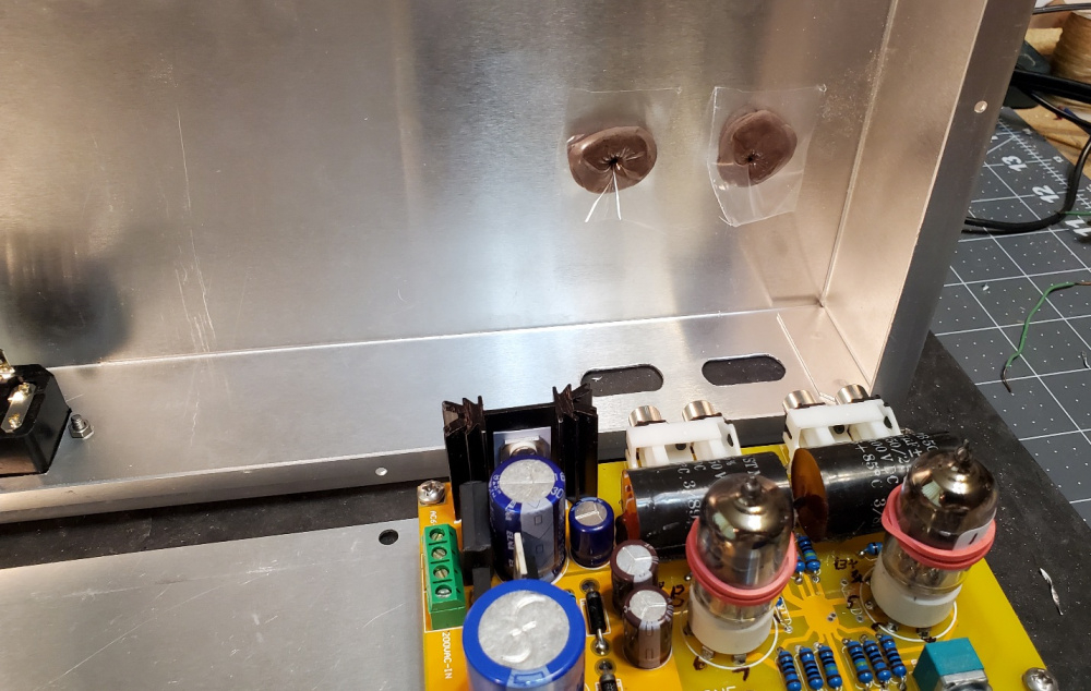
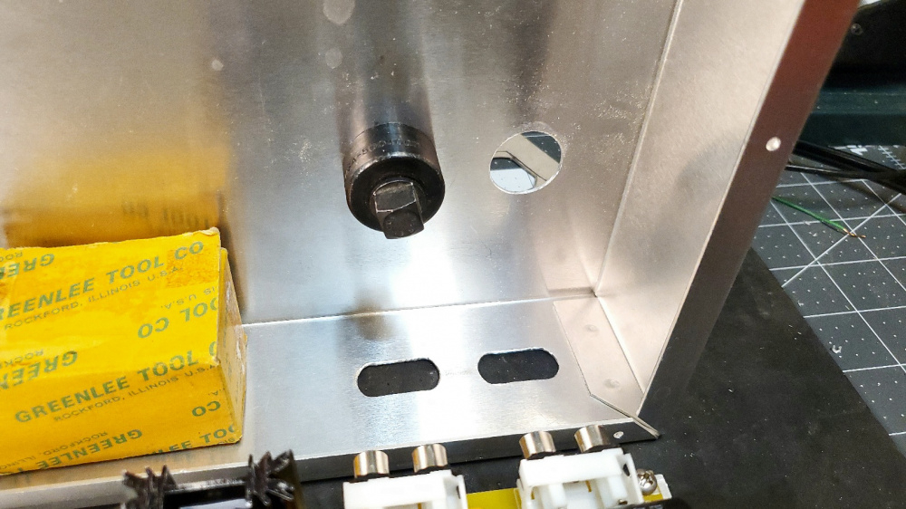
I then drilled a small 1/8" pilot hole in the center of each tube's impression:
Then increased both holes to 7/8" diameter:
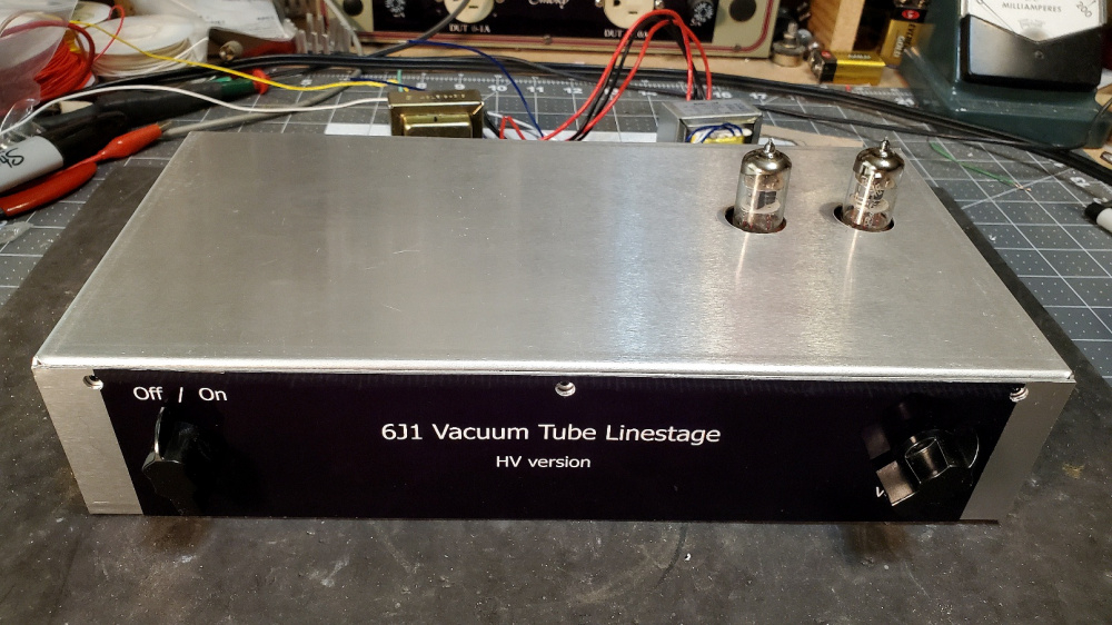
I could only raise the PCB a total of 1" using standoffs because I needed to keep the volume control knob near the center of the front panel. So, the tubes only stick out the top panel about 1/2". The glow of the filament, however, is still visible at this relatively low height.
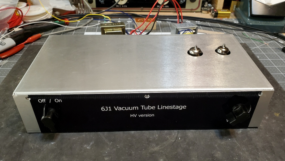
If I install 3/4" high tube socket savers, then the tubes will be 1-1/4" proud of the top panel and it will look like the picture below (I don't have socket savers yet, I used small 3/4" blocks of wood to raise the tubes for the photo). I think this probably looks better, but the lower profile would provide better EMI and RF shielding of the tube elements. Which one would you go with? By the way, I plan to add walnut side panels that partially wrap around the front panel and cover up the exposed aluminum. Should look pretty cool when I get it all buttoned up.
I could spare a top mount transformer cover and 50kohm aliexpress "alps" pot if you want it.
Thanks for the offer, Drew. The alps pot would certainly be better in terms of audio quality, I know. But the cheap little PCB mount pot is not too bad in terms of noise or intermittant wiper action. It keeps the signal path very short, so if I replaced it with an alps, the preamp would probably pick up more noise from the extra wiring. Also, I already have the space marked out for the xformer (s) and am beginning to drill and and wire up the remaining parts. Should have everything buttoned up and ready for REW FR and distortion testing in a few days. I'm also roughing out the circuits and loading the data into LTspice to see if I can "improve" upon this simple circuit. Thanks again.
Drew & Ani, I got the new LM7806 regulator chips from Mouser and tested one of them in the preamp. I get pretty much the same voltages as before, so the original LM7806 chips are probably OK. The new chip gives me 5.6vdc on the heaters instead of 5.4vdc using the original chip. The voltage between the rectifier and LM7806 is 7.10vdc (was 7.15vdc using the original chip). I think the basic problem is that the 6v transformer winding simply does not create a high enough voltage to bias the chip. Not a big problem, though, as the circuit seems to work OK at 5.4vdc.
On a related note, while I was browsing and ordering from Mouser, I found a small Triad 10VCT transformer rated at 600ma. Very small, PCB mount type. Really cheap. I tested it today and it works great. Gives me 6.0vdc on the heaters with only about 2mv of AC ripple. The heatsink on the 7806 chip gets up to about 120F after about 30 minutes, so I think I will add a 2 ohm 10W dropping resistor in series with the secondary to drop the incoming AC voltage just a tad. This should keep the LM7806 heatsink at about 100F or less. I'll make a little PCB board for the xformer+resistor and then mount it on standoffs next to the other xformer. Here is a link:
https://www.mouser.com/ProductDetail/Triad-Magnetics/F10-600?qs=Fg5d7evCualiF4rTkBFrSQ==
Bill, is the 6V of the new transformer significant compared to the 5.4V of the stock? Is this something you recommend we try out and install?
Like the recessed look - a bit different from the usual exposed tube stuff.
And it looks like my Musical Paradise Tube DAC MP-D1 MK3 (currently discontinued) - The tubes barely peek out
Stock images from the website and link.
https://www.musicalparadise.ca/store/index.php?route=product/product&path=66&product_id=98
Ani, I did not notice a difference in the hum level using the 6V of the new transformer compared to the 5.4V of the stock. However, I have only played a few music selections at this point. The raw PCB was unshielded, without an enclosure, and not properly grounded. There was a little hum because of this, so I don't think I can make a valid comparison at this time. I need to get the PCB buttoned up in the final enclosure, with all the star grounding wires properly connected. Then I can do a valid a/b listening comparison of the two power supplies by swapping connections back and forth. I also want to run an RTA plot in REW, comparing the noise floor generated by each filament supply. My feeling is that I will be unable to see or hear a difference, but this is only a guess at this point.
Thanks for the DAC pics, Ani. They really look cool.
How about a pair of steel washers, polished with brasso to make them look pretty?
Or maybe drill, tap, & mount them on 1/4" standoffs?
Some more progress:
I DIYed a little circuit board for the small Triad 10V transformer so that I could mount it with standoffs. This xformer's secondary measured 11.3vac under full load, so I dropped this to about 9vac with a 5 ohm 5W series resistor (see pic). This then produces about 9vdc after the rectifier and a tightly regulated 6vdc after the LM7806 regulator chip. Heatsink stays at about 101F or so after 30 minutes run time. Resistor gets up to about 106F, which feels hot, but not too hot. Seems to work very good and there is only about 2.5mv of AC ripple (120Hz) riding on the 6vdc.
I have it all wired up and am ready to begin my final measurements and listening tests.
For future reference in aligning the pot shaft to the panel mounted knob, I have used this sort of U-joint in the past and still have a small box of them somewhere in my shop - I'll try to dig them out to see if they are suitable for this application.
https://www.amazon.com/Befenybay-Universal-Joint-Coupling-Screws/dp/B07V9NW3V8/ref=sr_1_1?s=industrial&sr=1-1
Excellent tip! I'll have to add a set of these on my next Amazon order. Looks like the perfect solution. The universal joint would be able to easily make up for small amounts of DIY alignment error. I was probably just plain lucky to get an almost perfect alignment on my first try! The rubber vacuum hose idea will compensate for a little bit of error, but not much. With the universal joint, you could probably turn a 45 degree corner and still be OK.
Just the washers gives a real nice finished look. But if worried about the tubes safety I suppose the standoffs give best protection.
I can nickel plate them for you Bill. PM me if you're interested.
Those washers look good...!
Bill - let me send you these aluminum things. I have no idea what they were for. Something for Rockwell/Collins. They are aluminum and the hole is about 1". They just need a little polishing.
Thanks for the offer, Tom! Those look really cool, with a nice waveguide type bevel. Wish I could use them, but I am afraid that they may be too large in diameter. The washers I used in the above photo are 1.5" in diameter and, as you can see, the two washers almost hit each other when centered on the tubes. The distance between the two washers is about 0.2" So, the maximun diameter of any ring is therefore 1.5 + (.2/2) = 1.6" Otherwise they will hit each other. The inside diameter of my washers is 0.812" and the outside diameter of the 6J1 tube is 0.70" The hole that I cut in the chassis top is 0.875" and clears the 6J1 tube by 0.175". So if I tried to use your rings, I would probably have to truncate the sides of the rings and then widen my 7/8" chassis hole out to 1".
Ah yes, I didn't even think about the tube spacing.
@ani_101 , I spent a few hours listening to the Ali Express 5.4vdc filament hookup verses the Triad 6vdc filament hookup. (swapping the transformer wires back and forth on the PCB terminals and listening). The hum level is extremely low with both voltage hookups. With the volume control on the 6J1 preamp and my bench Lepai 2020 amp turned all the way up, I can barely hear any hum or hiss from the speakers. I have to put my ear within a few inches of the woofer to hear anything at all. I also played several music selections and could hear no difference between the 5.4v and 6v transformers. Both sounded very good.
Now, I know from experience that when you run a vacuum tube at a lower than specified filament voltage, this reduces the transconductance of the tube. This, in turn, will raise the output impedance at the plate of the tube, all else in the circuit being equal. The tube therefore will roll off the high frequencies a little bit sooner when driving into the same interconnect cable capacitance and power amp input impedance load. So, I tested and compared the frequency response of the 5.4v and 6v transformers to see if this made a difference. It did not. On my scope, both hookups are ruler flat out to 10kHz and only down about 0.1dB at 20kHz. The -3dB point is about 120kHz. So, in answer to your question, there is no need to use the Triad 10V transformer to boost the filaments to 6vdc. The original xformer should work just fine at 5.4vdc.
I tested this preamp's gain at 1kHz. With 146mv RMS at the input (yellow trace), it produces 2.27v RMS at the output (blue trace). This is a gain of 15.54 times or 23.83dB! Wow! This is alot of gain. If distortion is high, this preamp might be a candidate for installing a feedback mod. The other 6J1 preamp only had about 18dB of gain in stock form. And we reduced this down to about 6 to 8dB using negative feedback and other mods.
I also did a 10kHz square wave test. Here is what the input verses the output looks like. No ringing. The slight rounding is due to the -3dB roll off at 100kHz.
That much gain makes it unusable. I built my tube preamp as a cathode follower so it actaully has a gain of -0.92 dB. None of my power amps need a preamp with gain.
How much can feedback help with this?