If I may make a suggestive process, since you are shooting for 1st order slopes. Watch individual acoustic phases as you go.
I would look at them like we discussed in the theme thread. Make them -6dB individual responses at roughly 1800-2k, using either single components or with added series contour filters. Cap plus cap parallel to resistor for tweeter, and coil plus coil parallel to resistor for woofer. This will allow you to start the rolloff as in intended. I would suggest 5.6uF for 1st component on tweeter, and 1.5mH on woofer 1st component. Once the tilt is right, tweak the other 2 for best results. Likely 0.25 to 0.5mH, and 3.3-4.7uF. Choose resistance for amount of damping needed.
Then, add either the notch on the tweeter and notch of same style on woofer, or minimally a shunt CR on woofer, and shunt LR on tweeter. For the CR, start with a small value cap, say 3.3uF and 6 ohm. The LR should likely be 2.5mH and 6 ohms starting.
Then once you are happy with the meld at -6dB, and the slope increases to either side of the xover point, if you still have breakup, apply notches across drivers. For woofer, guess is 0.1uF, 0.5mH, start at 4 ohms. Your tweeter notch is likely close here to both damp Fs, and tank rolloff.
Looking at Brad's graph he crossed around 2khz. Looking at the phase lines, the phase of the woofer and tweeter are right on top of each other at that point and very close an octave below and above. (Green circles/blobs added)
I'll download the frds and load them into VituixCAD. See what I can come up with. If I paint myself into an electrical corner, I'll "cheat" a little bit by looking at your schematics!
@4thtry said:
I'll download the frds and load them into VituixCAD. See what I can come up with. If I paint myself into an electrical corner, I'll "cheat" a little bit by looking at your schematics!
@Eggguy said:
You might have noticed that I changed the name of the thread.
I'm glad you posted that...I thought I was losing it.
The chubby faced eggs are not going to be ready for a while. I have one assembled but it has issues. I could not get the curved laminations compressed enough to snap into the groove and I cracked the MDF, but I am able to work on my crossovers and my knowledge of them.
Downloaded the files. I get a good tweeter modeling offset of 0.53 inches (or 39.5 microseconds) using the tweeter on axis, woofer on-axis, and woofer+tweeter combined files. But when I attempt to load the tweeter and woofer 60 degree off axis FRD's into the model, they appear to have been measured using a differenct amplifier volume control setting. This is not a problem, as I can scale them up by 8dB in VituixCAD to match the SPL of the on-axis curves. But the 8dB scaling is just an assumption on my part. I just wanted to verify this before proceeding.
Yes, I did them on different days. This morning was the first time I rigged up a lazy susan tray for off axis measurements. The woofer measurements are also on tweeter axis. Thanks
Also I have been wondering how simulation software can do it properly without knowing driver spacing? I guess the combined response curve shows the effects of mutual coupling between drivers.
When taken on same axis, you need a timelock via dual channel mic setup or 3 measurements with USB style.
FR on one (design) axis of tweeter, woofer, and woofer+tweeter. This will allow setting your acoustic center or Z axis, and the Y and x are already in the FR measurements.
Comments
If I may make a suggestive process, since you are shooting for 1st order slopes. Watch individual acoustic phases as you go.
I would look at them like we discussed in the theme thread. Make them -6dB individual responses at roughly 1800-2k, using either single components or with added series contour filters. Cap plus cap parallel to resistor for tweeter, and coil plus coil parallel to resistor for woofer. This will allow you to start the rolloff as in intended. I would suggest 5.6uF for 1st component on tweeter, and 1.5mH on woofer 1st component. Once the tilt is right, tweak the other 2 for best results. Likely 0.25 to 0.5mH, and 3.3-4.7uF. Choose resistance for amount of damping needed.
Then, add either the notch on the tweeter and notch of same style on woofer, or minimally a shunt CR on woofer, and shunt LR on tweeter. For the CR, start with a small value cap, say 3.3uF and 6 ohm. The LR should likely be 2.5mH and 6 ohms starting.
Then once you are happy with the meld at -6dB, and the slope increases to either side of the xover point, if you still have breakup, apply notches across drivers. For woofer, guess is 0.1uF, 0.5mH, start at 4 ohms. Your tweeter notch is likely close here to both damp Fs, and tank rolloff.
InDIYana Event Website
Good stuff buddy. New guy appreciates it.
New guy is having some difficulty digesting Ben's information.
I will try again tomorrow
Post a graph with the individual driver responses and phases and everyone will chime in.
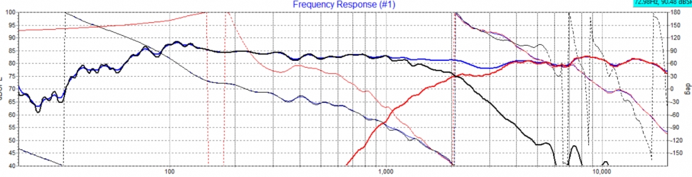
Did I do it right?
I'm guessing, no.
We are looking for something like this.
https://www.jfcomponents.com/
@Eggguy
Looking at Brad's graph he crossed around 2khz. Looking at the phase lines, the phase of the woofer and tweeter are right on top of each other at that point and very close an octave below and above. (Green circles/blobs added)
Seeing a ~6db summation of the resultant response above the crossing point of the individual slopes is an indicator good phase summation as well.
More curves for you guys. Horizontal polars 0-60
Think of it as a crossover competition, except I always win.
I win by being the recipient of knowledge by all who participate.
You might have noticed that I changed the name of the thread. I may eventually change it again to something like. Thanks help helping a dumbass.
I'll download the frds and load them into VituixCAD. See what I can come up with. If I paint myself into an electrical corner, I'll "cheat" a little bit by looking at your schematics!")
I'm glad you posted that...I thought I was losing it.
Thanks Bill
The chubby faced eggs are not going to be ready for a while. I have one assembled but it has issues. I could not get the curved laminations compressed enough to snap into the groove and I cracked the MDF, but I am able to work on my crossovers and my knowledge of them.
It’s a journey
Downloaded the files. I get a good tweeter modeling offset of 0.53 inches (or 39.5 microseconds) using the tweeter on axis, woofer on-axis, and woofer+tweeter combined files. But when I attempt to load the tweeter and woofer 60 degree off axis FRD's into the model, they appear to have been measured using a differenct amplifier volume control setting. This is not a problem, as I can scale them up by 8dB in VituixCAD to match the SPL of the on-axis curves. But the 8dB scaling is just an assumption on my part. I just wanted to verify this before proceeding.
Tweeter scaling:
Woofer scaling:
Yes, I did them on different days. This morning was the first time I rigged up a lazy susan tray for off axis measurements. The woofer measurements are also on tweeter axis. Thanks
That it is
I often say to friends that I am an analog guy in a digital world, so I welcome the challenge.
Can you post the impedance files as ZMA please.
I knew something was not quite rite.
If computers are so smart, why do they need my guidance?
Also I have been wondering how simulation software can do it properly without knowing driver spacing? I guess the combined response curve shows the effects of mutual coupling between drivers.
When taken on same axis, you need a timelock via dual channel mic setup or 3 measurements with USB style.
FR on one (design) axis of tweeter, woofer, and woofer+tweeter. This will allow setting your acoustic center or Z axis, and the Y and x are already in the FR measurements.
InDIYana Event Website
What Ben said...
I did Xsim for the first time today, and its cool. I think I am now an expert.