To me, it would be more a matter of using a very simple, low part count circuit. But if and only if you can get away with it. Make the signal path as short as you can. Given the fact that most drivers do not have sufficient overlap, you generally end up with at least 2nd order when using 1st order parts, then transitioning to even higher orders later on.
Odd order filters, including 1st order are always 90 degrees out of phase at the cross over point. Flip one driver 180 degrees the phase is still 90 degrees out so there's no change at the cross over point.
Yes the component count does become ridiculous after all of the impedance comp. and notches and such. If I want simplicity, and I do, that woofer is not a good candidate. And I also run the risk of tweeter damage rolling of 2nd ord. acoustic at 1450.
Here is my Chubby 1st order attempt. Xover is 1.9kHz with a true 6dB/octave acoustical slope for the first 1.5 octaves above and below the xover frequency. Slopes transition to 12dB/octave below 800Hz and 24dB/octave above 5kHz. Response is very smooth on-axis from about 300Hz to 20kHz. In-Room and Power Response curves are also very smooth and downward sloping from about 300Hz to 10kHz. Phase tracking is not overlapping or parallel, but seems relatively smooth throughout the xover region. I don't know how important this is. I was targeting the On-Axis, Listening Window, and Power Response curves and allowing the phase tracking to do whatever it wanted to do.
Here is a description of crossover parts used. It is a "simple" 6dB/octave electrical with a bunch of notches to correct problems:
1) 2 ohm/3.6uF: High frequency contour to smooth out response from 5kHz to 20kHz.
2) 36uF/18 ohm: Tweeter zobel to suppress the 880Hz impedance peak of the Supreme tweeter.
3) 470nF/8.2 ohm: 5kHz notch to suppress woofer breakup.
4) 7.5 ohm/43.2uF/392uH: Woofer parallel notch filter to flatten the 1kHz peaking problem.
5) 6.2uF: Tweeter 1st order high pass filter.
6) 1mH: Woofer 1st order low pass filter.
Let me know what you think of my decision making process. I could probably keeping working on this to pound it even flatter or address other problems, but at some point you have to stop and take a look at where you are.
1) Single channel measurements are valid at 1 meter, not the 2.5 meter listening distance.
2) Single channel measurements suffer from a small amount of phase error on the polar plots.
3) OmniMic can only measure from 0-90 degrees. This causes error in power and In-room curve slopes.
4) There is also a 4th item, but I forgot what it was.
For reference, here are the VituixCAD Driver screens for the Woofer and Tweeter than I used. Note that the tweeter screen applies 39 microseconds of delay to align the on-axis phase:
@jhollander said:
Odd order filters, including 1st order are always 90 degrees out of phase at the cross over point. Flip one driver 180 degrees the phase is still 90 degrees out so there's no change at the cross over point.
This makes sense. So then, phase tracking for the tweeter and woofer should be overlapping for even order acoustical filters. And phase tracking should be parallel, offset by 90 degrees, for odd order acoustical filters. At least, that would be the ideal, if you are trying to get your crossover to follow the theory of how even or odd order filters should actually behave. The next question would be: Is this audible? If you "cross the phase curve streams", so to speak, does this have a negative audible effect on how the two drivers blend together? (Sorry, that was a bad ghostbuster's joke).
Forgot to mention. The tweeter phase is reversed in the above model. Here is what the model looks like when the two drivers are connected in phase. Not a good looking reverse null or flat response. It becomes somewhat wonky looking due to the non-parallel phase tracking situation.
My thoughts...
The ripple in the top octave for the woofer due to the tank notch is only at -20dB from reference. This could be audible. The breakup is also only -20dB down, but being a high-mass midbass could possibly be okay.
One thing to remember is that 1st order acoustic can include the shunt components of higher orders, but the values will need to be tweaked and shifted further out of band than usual.
I plan on playing with this in sim for on axis alone in the near future, just to give it a try.
Whoops. Houston, we have a problem. I just entered all the values for my 1st order crossover in XSim, as a sanity check, to make sure that I would get the same results in both VituixCAD and XSim using the same on-axis FRD's and ZMA's. If you enter all the data properly, both programs should give identical results. Turns out, I entered the 39 microsecond delay backwards in VituixCAD. I should have entered it as a NEGATIVE -39 microseconds. The negative value of -0.53 inches in XSim is equivalent to a -39 microsecond delay in VituixCAD; not a positive +39 microseconds!!! So, I will have to re-do my VituixCAD model tomorrow, using the correct delay, and then re-post it with revised values. Sorry about that. Hopefully you have not ordered parts.
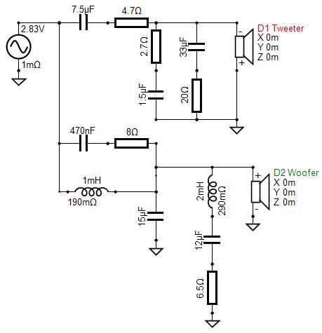
Here is the revised 1st order xover, this time using the correct negative (-39us) tweeter delay. Xover is 1.8kHz with a true first order acoustical slope for the first 1.5 octaves on the tweeter and the first octave on the woofer. The slope then transitions to 12dB/octave on both drivers. Per Wolf's suggestion above, I added a small 15uF shunt cap to address the 5kHz breakup on the woofer. It now looks much better in terms of the breakup, but the slope transitions to 2nd order at higher frequencies to accomplish this. Phase tracking now looks a little bit better than before, more of a parallel type tracking instead of criss crossing type. It now has a reverse null that looks like a compromise between an even and odd order crossover (which is what this is). The tweeter is connected in reverse polarity to achieve flat response. Power and In-room curves look fairly smooth and downward sloping.
Here is the tweeter driver screen showing the correct delay:
Here is the XSim "sanity check" model using the same model delay:
I tried to use parts commonly available from parts express. Inductors are 257-650 and 257-654. Caps are 027-429, 027-412, 027-944, 027-406, 027-432 and 027-430. Resistors are 006-2.7, 006-4.7, 006-20, 004-8, and 006-6.5
I don't get it either Craig, but in order to get this notion out of my head, I feel like I need to see it through. Also I don't mind being different. Plus I got Bill on my team. Team Schwefel. The diffracto duo. I'm the sidekick.
Comments
Why the focus on ELECTRICAL order rather a specific ACOUSTIC slope? I (kinda) get why people might prefer first or second order acoustical slopes.
To me, it would be more a matter of using a very simple, low part count circuit. But if and only if you can get away with it. Make the signal path as short as you can. Given the fact that most drivers do not have sufficient overlap, you generally end up with at least 2nd order when using 1st order parts, then transitioning to even higher orders later on.
I guess this is why the Woofer Assisted Wideband alignment became popular - to obtain the best driver overlap.
Odd order filters, including 1st order are always 90 degrees out of phase at the cross over point. Flip one driver 180 degrees the phase is still 90 degrees out so there's no change at the cross over point.
Is it possible to use an inductor in series with the woofer and a series capacitor on the wideband to realign the drivers phases?
Yes the component count does become ridiculous after all of the impedance comp. and notches and such. If I want simplicity, and I do, that woofer is not a good candidate. And I also run the risk of tweeter damage rolling of 2nd ord. acoustic at 1450.
When my Wife wakes up I think I might ask her if I can buy some supreme woofers to go with my supreme tweeters.
I might, but I probably won't.
Just tell her they were on sale, and you did so to save $ by not needing to buy extra components.
Shoulda bought them a few years ago when they were half the price, like I did.
BTW, no first order acoustic slopes on those either, I wound up 4th order.
InDIYana Event Website
Better?
Can’t see anything. Those files are just a bunch of numbers.
https://www.jfcomponents.com/
It has some large value Caps
Oopsies
I'm living up to the F in FNG
Here is my Chubby 1st order attempt. Xover is 1.9kHz with a true 6dB/octave acoustical slope for the first 1.5 octaves above and below the xover frequency. Slopes transition to 12dB/octave below 800Hz and 24dB/octave above 5kHz. Response is very smooth on-axis from about 300Hz to 20kHz. In-Room and Power Response curves are also very smooth and downward sloping from about 300Hz to 10kHz. Phase tracking is not overlapping or parallel, but seems relatively smooth throughout the xover region. I don't know how important this is. I was targeting the On-Axis, Listening Window, and Power Response curves and allowing the phase tracking to do whatever it wanted to do.
Here is a description of crossover parts used. It is a "simple" 6dB/octave electrical with a bunch of notches to correct problems:
1) 2 ohm/3.6uF: High frequency contour to smooth out response from 5kHz to 20kHz.
2) 36uF/18 ohm: Tweeter zobel to suppress the 880Hz impedance peak of the Supreme tweeter.
3) 470nF/8.2 ohm: 5kHz notch to suppress woofer breakup.
4) 7.5 ohm/43.2uF/392uH: Woofer parallel notch filter to flatten the 1kHz peaking problem.
5) 6.2uF: Tweeter 1st order high pass filter.
6) 1mH: Woofer 1st order low pass filter.
Let me know what you think of my decision making process. I could probably keeping working on this to pound it even flatter or address other problems, but at some point you have to stop and take a look at where you are.
Also keep in mind the limitation of this model:
1) Single channel measurements are valid at 1 meter, not the 2.5 meter listening distance.
2) Single channel measurements suffer from a small amount of phase error on the polar plots.
3) OmniMic can only measure from 0-90 degrees. This causes error in power and In-room curve slopes.
4) There is also a 4th item, but I forgot what it was.
For reference, here are the VituixCAD Driver screens for the Woofer and Tweeter than I used. Note that the tweeter screen applies 39 microseconds of delay to align the on-axis phase:
This makes sense. So then, phase tracking for the tweeter and woofer should be overlapping for even order acoustical filters. And phase tracking should be parallel, offset by 90 degrees, for odd order acoustical filters. At least, that would be the ideal, if you are trying to get your crossover to follow the theory of how even or odd order filters should actually behave. The next question would be: Is this audible? If you "cross the phase curve streams", so to speak, does this have a negative audible effect on how the two drivers blend together? (Sorry, that was a bad ghostbuster's joke).
Thanks Bill, I will build it and listen to it.
Forgot to mention. The tweeter phase is reversed in the above model. Here is what the model looks like when the two drivers are connected in phase. Not a good looking reverse null or flat response. It becomes somewhat wonky looking due to the non-parallel phase tracking situation.
My thoughts...
The ripple in the top octave for the woofer due to the tank notch is only at -20dB from reference. This could be audible. The breakup is also only -20dB down, but being a high-mass midbass could possibly be okay.
One thing to remember is that 1st order acoustic can include the shunt components of higher orders, but the values will need to be tweaked and shifted further out of band than usual.
I plan on playing with this in sim for on axis alone in the near future, just to give it a try.
InDIYana Event Website
Whoops. Houston, we have a problem. I just entered all the values for my 1st order crossover in XSim, as a sanity check, to make sure that I would get the same results in both VituixCAD and XSim using the same on-axis FRD's and ZMA's. If you enter all the data properly, both programs should give identical results. Turns out, I entered the 39 microsecond delay backwards in VituixCAD. I should have entered it as a NEGATIVE -39 microseconds. The negative value of -0.53 inches in XSim is equivalent to a -39 microsecond delay in VituixCAD; not a positive +39 microseconds!!! So, I will have to re-do my VituixCAD model tomorrow, using the correct delay, and then re-post it with revised values. Sorry about that. Hopefully you have not ordered parts.
^ Very diligent of you, Sir Bill!
Most excellent assistance for a most excellent craftsman's efforts.
Once again I am convinced that this path that I am on has a lot of good people on it as well.
Here is the revised 1st order xover, this time using the correct negative (-39us) tweeter delay. Xover is 1.8kHz with a true first order acoustical slope for the first 1.5 octaves on the tweeter and the first octave on the woofer. The slope then transitions to 12dB/octave on both drivers. Per Wolf's suggestion above, I added a small 15uF shunt cap to address the 5kHz breakup on the woofer. It now looks much better in terms of the breakup, but the slope transitions to 2nd order at higher frequencies to accomplish this. Phase tracking now looks a little bit better than before, more of a parallel type tracking instead of criss crossing type. It now has a reverse null that looks like a compromise between an even and odd order crossover (which is what this is). The tweeter is connected in reverse polarity to achieve flat response. Power and In-room curves look fairly smooth and downward sloping.
Reverse null now looks like this:
Here is the tweeter driver screen showing the correct delay:
Here is the XSim "sanity check" model using the same model delay:
I tried to use parts commonly available from parts express. Inductors are 257-650 and 257-654. Caps are 027-429, 027-412, 027-944, 027-406, 027-432 and 027-430. Resistors are 006-2.7, 006-4.7, 006-20, 004-8, and 006-6.5
That's sure a lot of parts to achieve sort of first order slopes. I don't get it.
I don't get it either Craig, but in order to get this notion out of my head, I feel like I need to see it through. Also I don't mind being different. Plus I got Bill on my team. Team Schwefel. The diffracto duo. I'm the sidekick.
Don't cross the streams.
How many reactive component are in an amplifier?