Site Links
Howdy, Stranger!
It looks like you're new here. If you want to get involved, click one of these buttons!
Quick Links
Categories
In this Discussion
Who's Online (0)
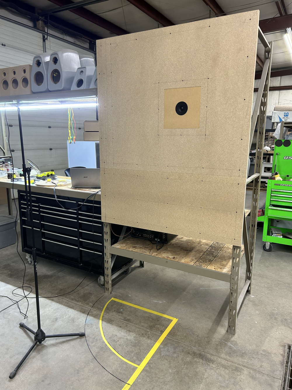
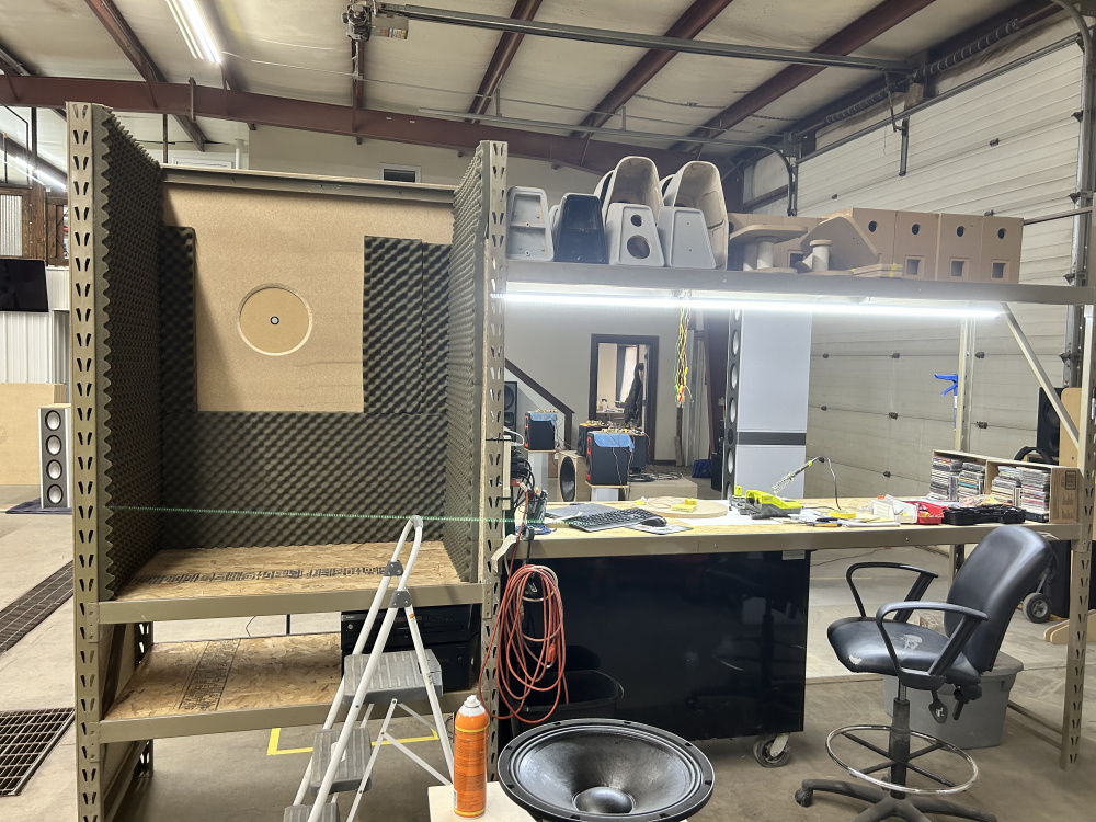
IEC test baffle.

I only made the up to 8in baffle. They start to get big after that. I still have to come up with some kind of turntable for the mic.


Comments
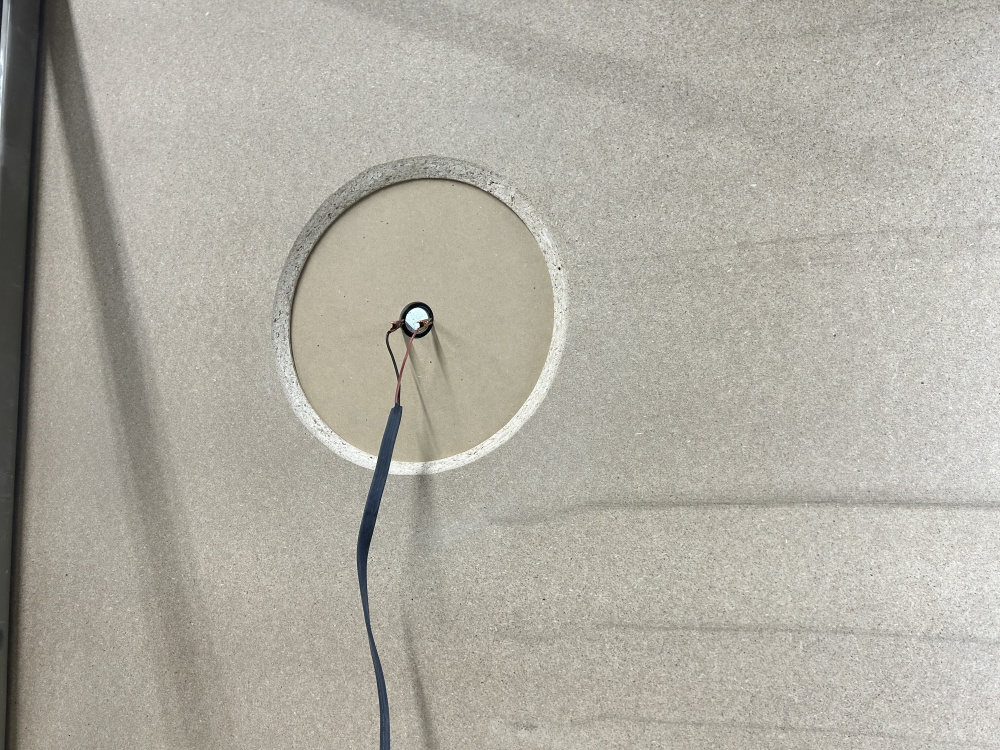
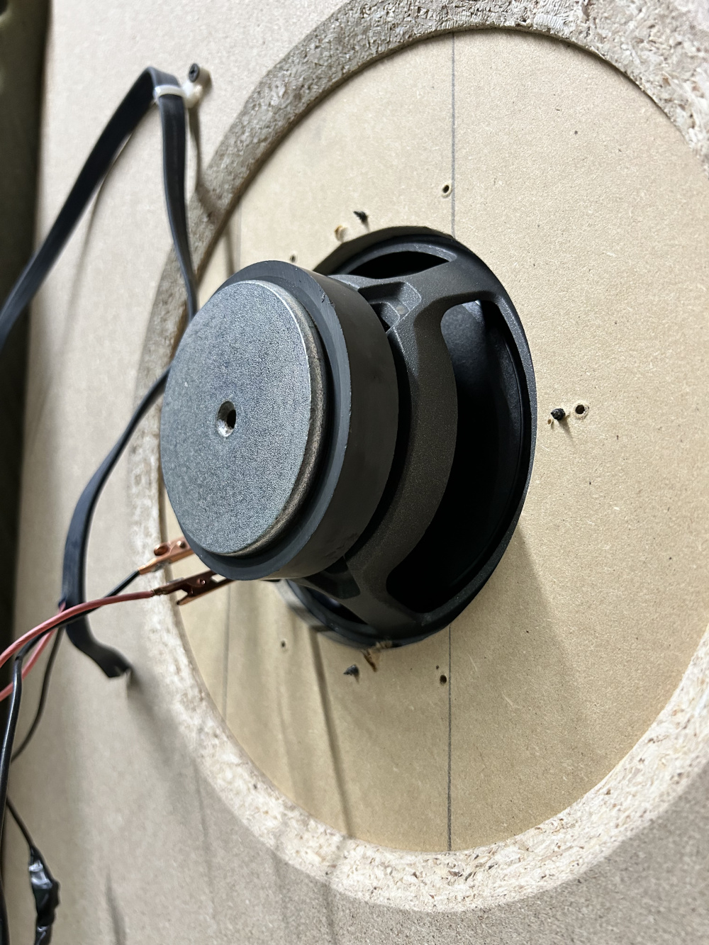
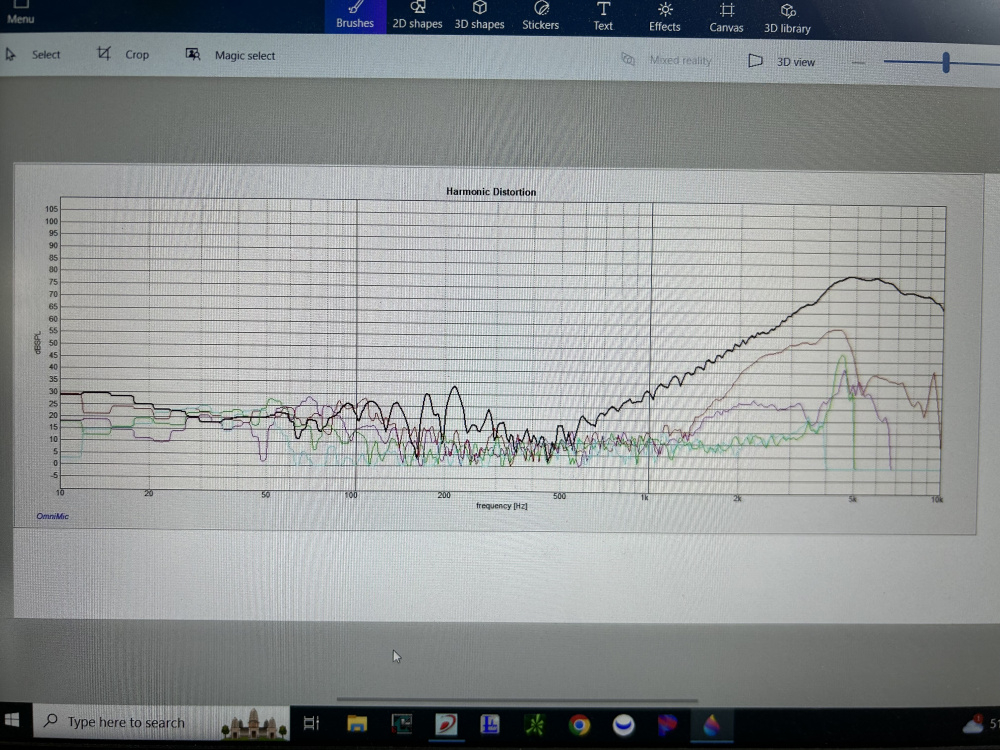
This is the tiny tweeter I used in my recent 3-way.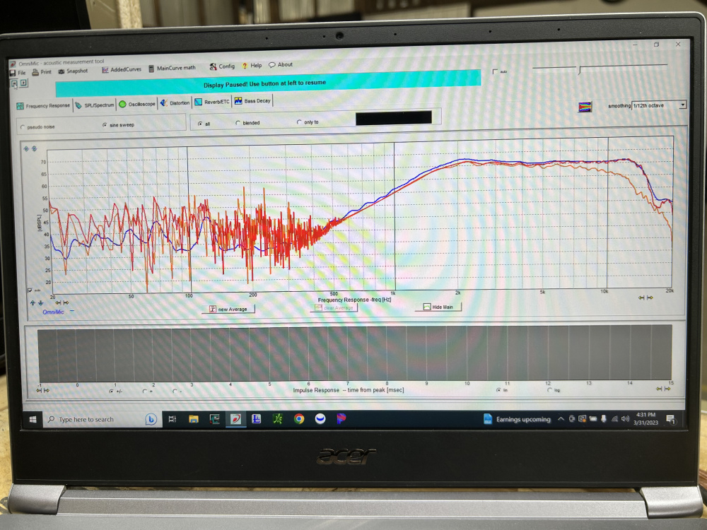
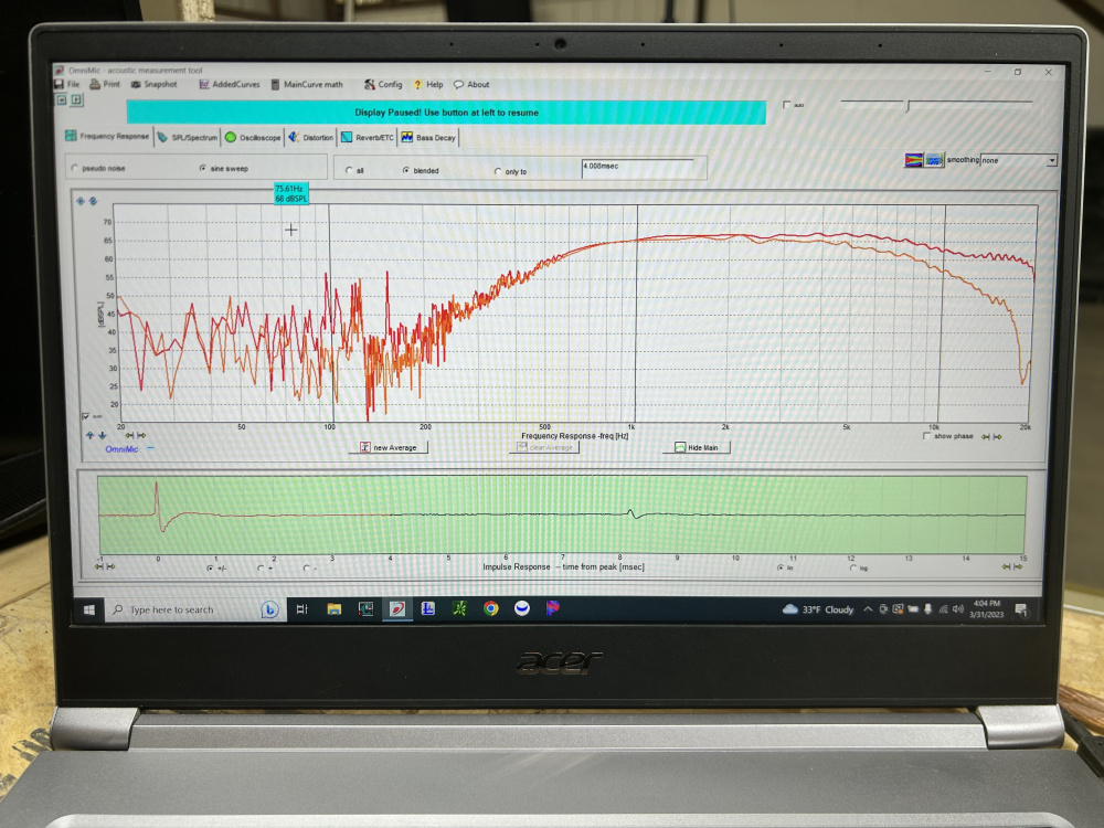
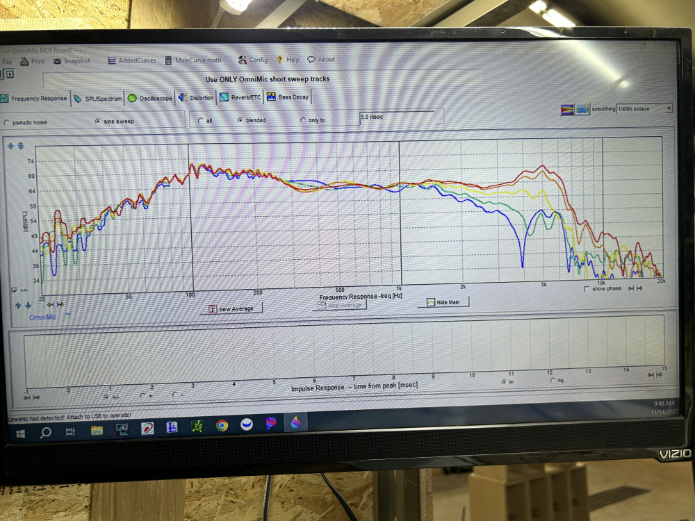
Orange 45deg no smoothing
Red 0deg no smoothing
Blue 0 deg no gate 1/12 smoothing
Should I be measuring with no gate? Info on this is slim on the internet.
https://www.jfcomponents.com/
It looks like the gate gets rid of the little ripples below 1K. Wish I had that much height to work with. Your gate time must get you down to under 200Hz?
I always set my gate based on the nearest reflective surface, which is generally the floor.
The floor is 6 foot from center of driver. But I didn’t really read anywhere if you had a gate your measurement with the baffle, we’re only talking tweeters here at the moment.
https://www.jfcomponents.com/
Window at first reflection always. I would only use un-windowed measurement for near field or room measurements.
The only time I measure with no gate is when I am doing near field (NF) type measurements, usually within about 1/4" from the cone. But if I am measuring at a distance where room reflections begin to influence the measurement, I would think that a gated measurement would be necessary.
I'm working on a plan with wheels to rotate my baffle plus speaker stand. Not that you asked, I'd add wheels to the rack, and a pointy piece of all thread to a small hole in the concrete to rotate the rack around. I don't like moving the mic.
I think Omni Mic, gated to first reflection in the impulse response window, blended, 1/48 smoothing gives me the best information. Because I'm in the basement in construction, I lay pillows or fiberglass insulation on the floor to mute the floor reflection. IIRC you can blow up the impulse window to better see the reflections.
Edit, your impulse window and first reflection is very clean compared to what I see.
Edit, I'd also use packing tape to smooth the transition between the IEC baffle and sub baffle
Thanks John. My rack (baffle) isn’t very moveable.😆. I think I have an idea for the microphone boom.
https://www.jfcomponents.com/
https://www.jfcomponents.com/
Do I have this to enclosed?
https://www.jfcomponents.com/
window can be doubled.
That won’t change 200-500 tho. As I read more about all this there really is no standard it sounds like everyone does it a little different.
https://www.jfcomponents.com/
It will make a difference. Increase your gate time from 4 msec to 8 msec. Your FR data will then be IEC IB data.
So do you always set it before first reflection? Can’t say I ever have.
https://www.jfcomponents.com/
I was hoping to get a better reading from 200hz and up. Mine looks nothing like peerless OG.
https://www.jfcomponents.com/
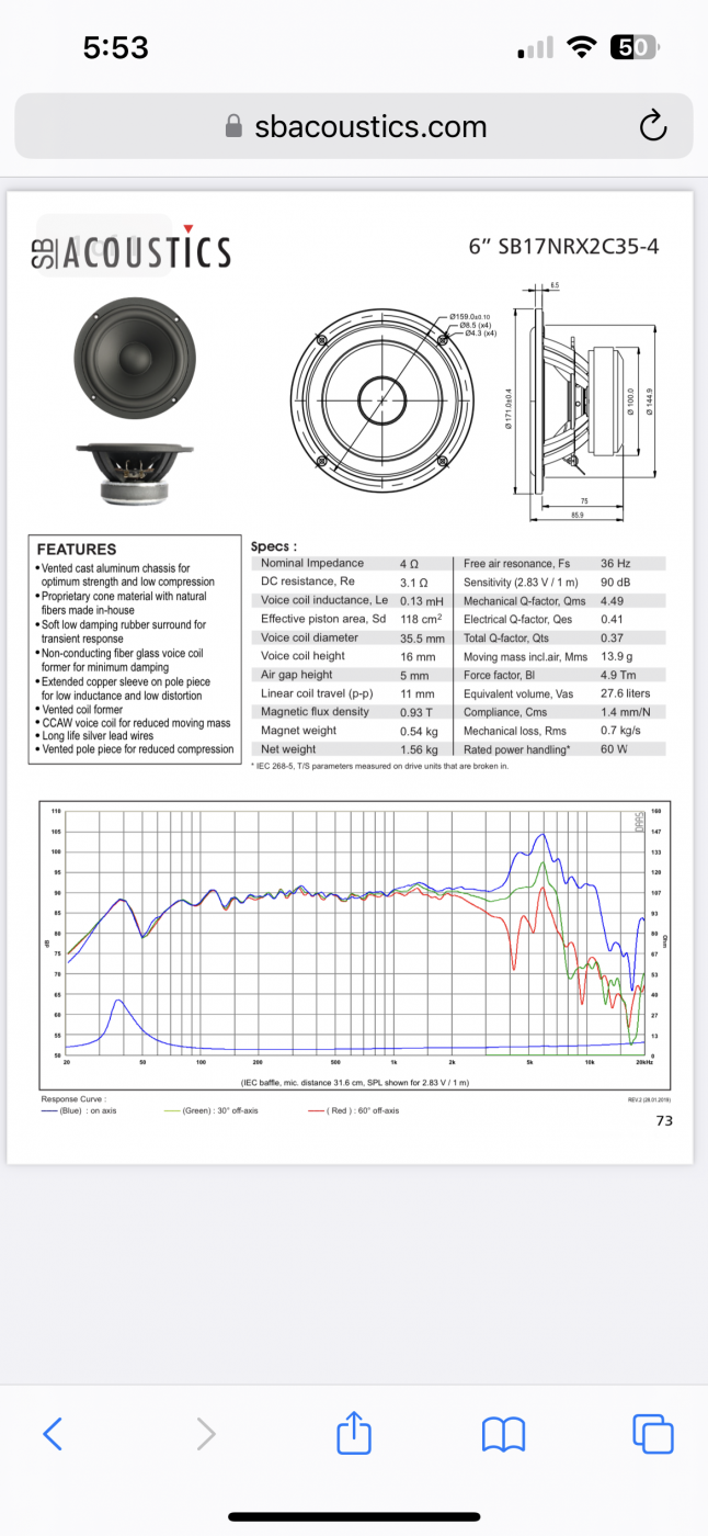
I want to make a baffle for this and see how this works. But it says 31.6 cm which equals 12 1/2 inches that’s what they do their measurements at?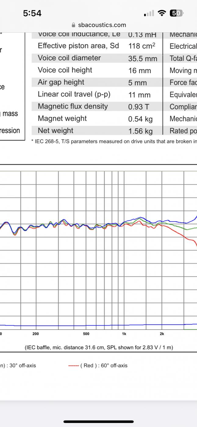
https://www.jfcomponents.com/
DIYers need to measure at 2.5 to 3 times the baffle width of the drivers in the actual box to ensure accurate interaction of the drivers and effects of the baffle. Measuring at 1m creates a replicable standard and exceeds the 2.5 to 3 times requirement. However, this is usually in a home environment and this requires gating and separate near field measures, merging, etc.
For infinite baffle there is no baffle and thus no 2.5 to 3 times the baffle width requirement. So measuring closer allows lower power to be used and longer gate times. Then they just adjust the actual lower power to match a standard 2.83v sensitivity.
Lol. That’s about the same info I’m getting from the internet. Do what you want and call it what you want.
https://www.jfcomponents.com/
I’m trying to get a standard of measurement for drivers. Not my own personal build.
https://www.jfcomponents.com/
SB likely measures without window hence all the wiggles on the low end in all their datasheets.
From Hificompass. He measures on 1650x850 mm baffle.
Thanks for your research. (I never even thought to look at hifi compass)
Im getting if I do enough drivers at my own standard then I will have something to compare to each other. Kinda like Zaph did.
I’ll be keeping this thing for my own measurements . It does measure tweeters well
https://www.jfcomponents.com/
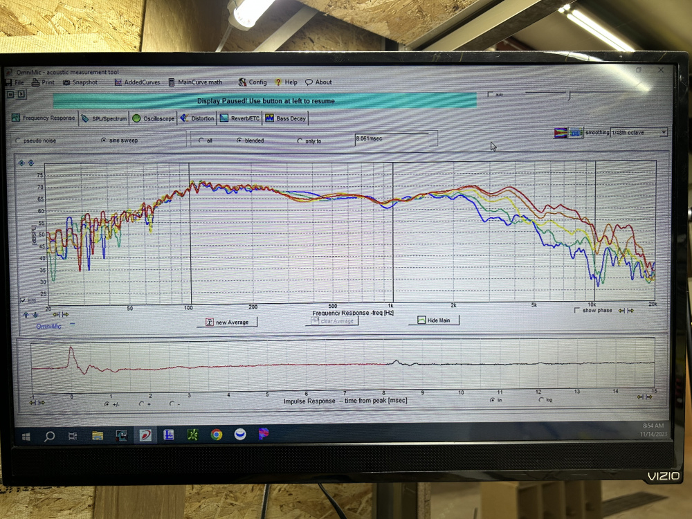
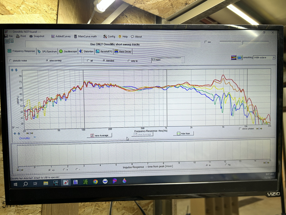
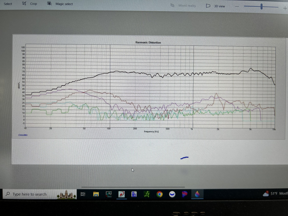
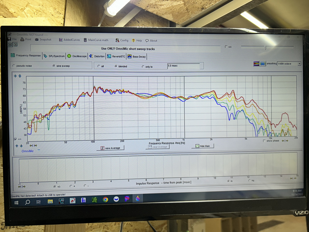
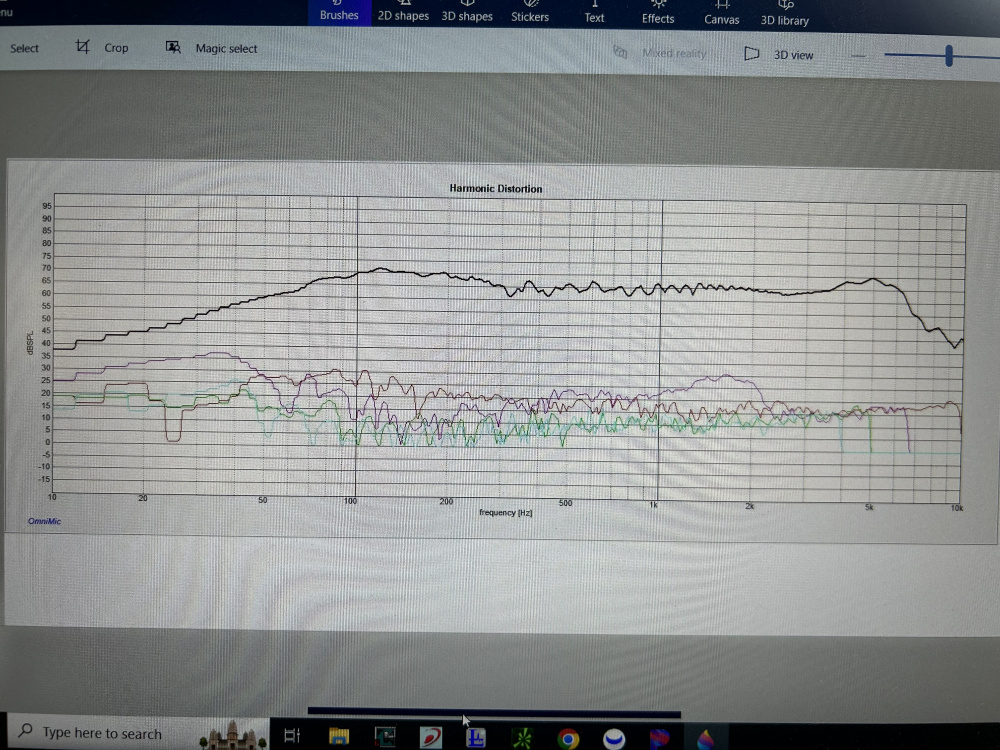
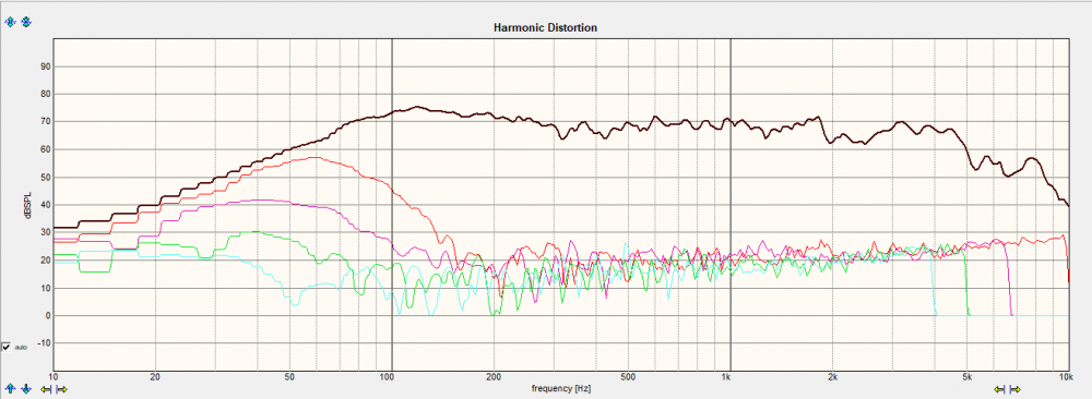
Did some IEC baffle testing this morning. I’m gonna post all my results in this thread in case someone needs a reference someday to one of these drivers. This will be a on going thread for me as I have lots of measurements to share.
All measurements taking:
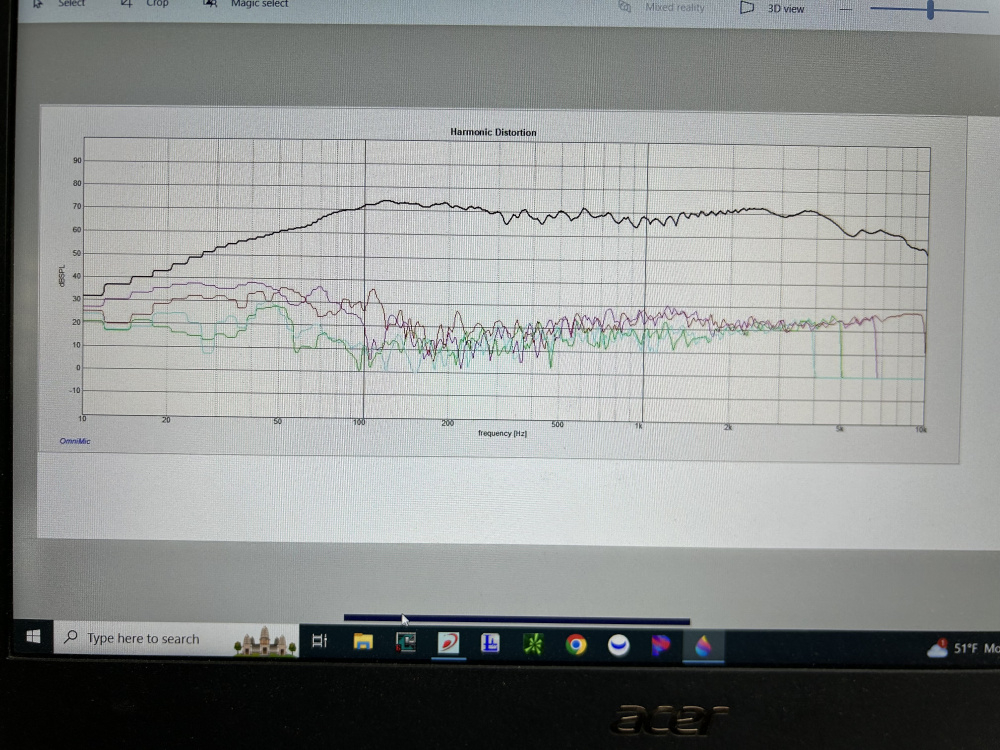
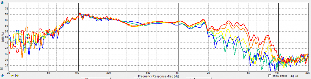
-1 meter distance on all FR and Distortion.
-0,15,30,45,60 degrees are my standard.
-8 ms gate
-2v
https://www.jfcomponents.com/
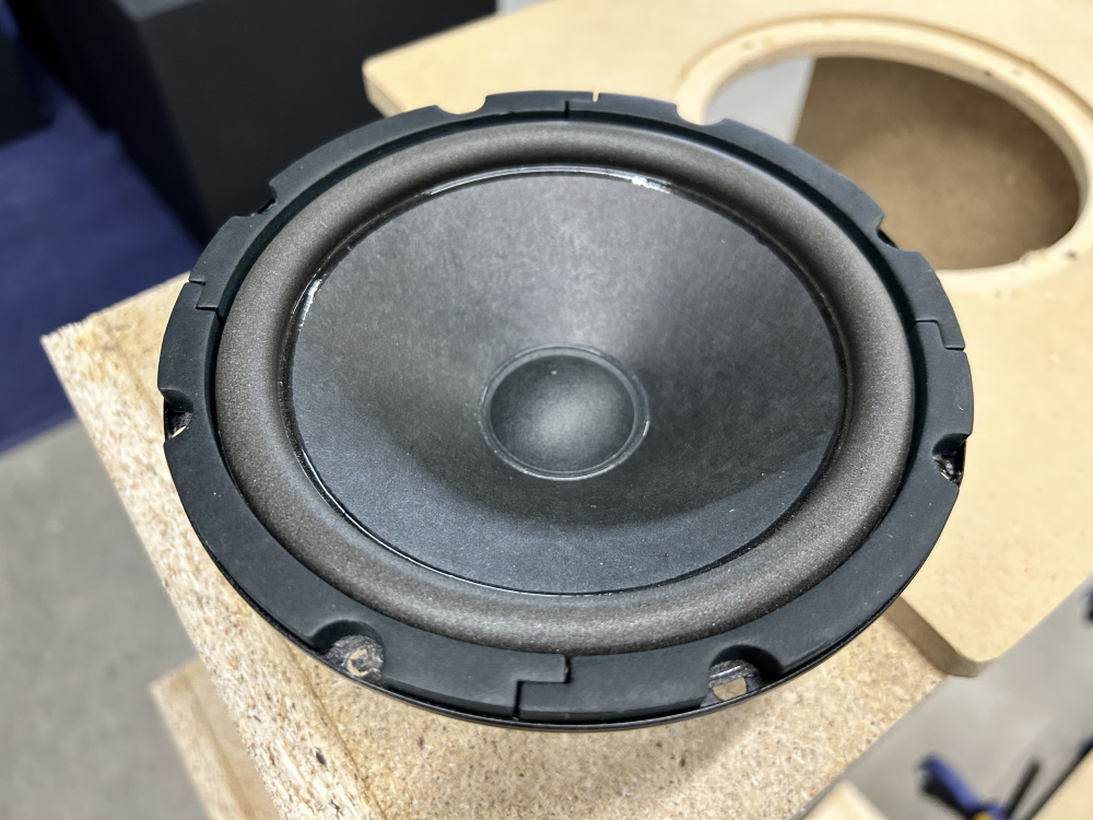
Hertz MP165p.3
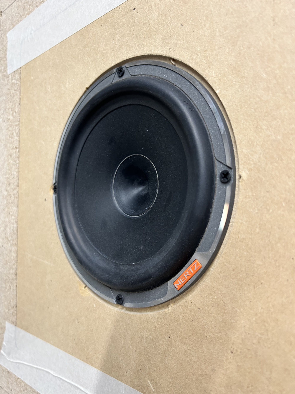
Freebies to me.
https://www.jfcomponents.com/
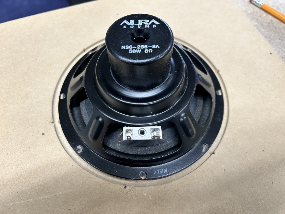
Aura NS6-255-8A
https://www.jfcomponents.com/
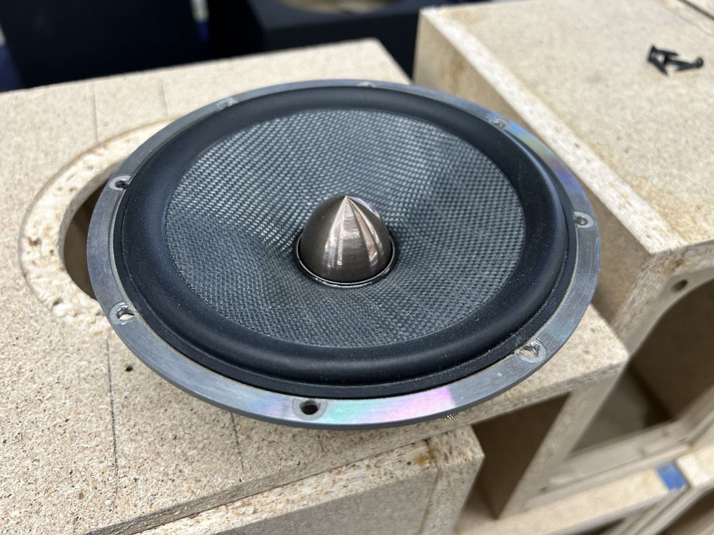
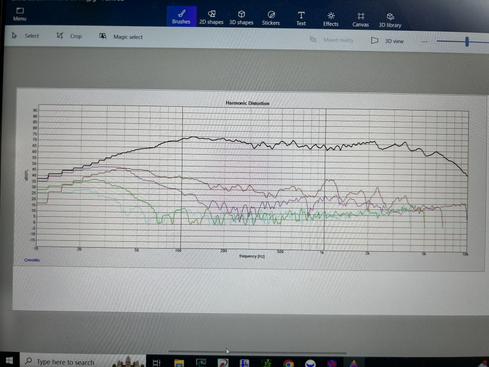
Chinese carbon M165.
https://www.jfcomponents.com/
Audison APX-4
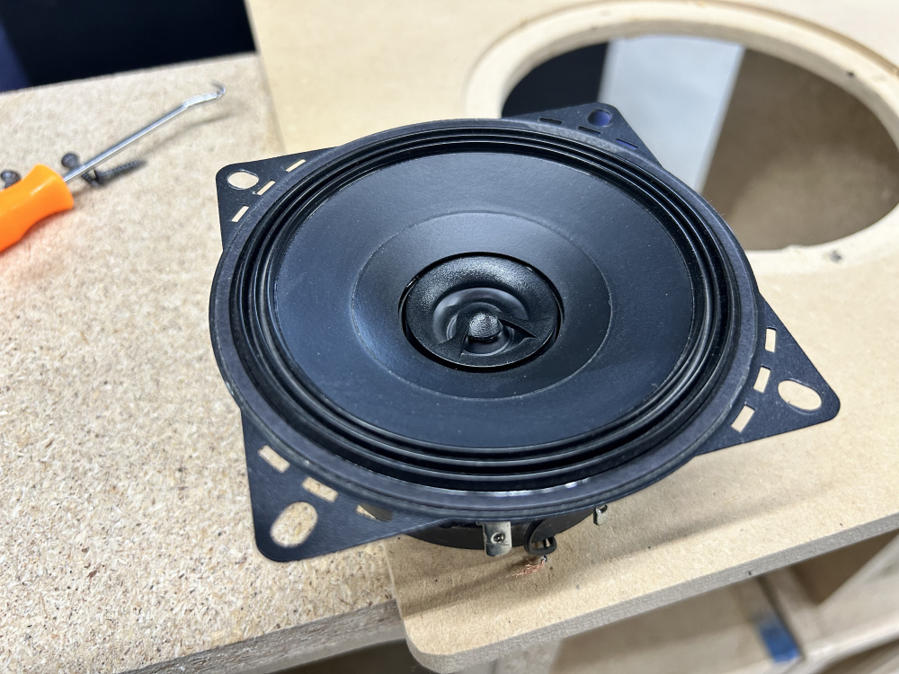
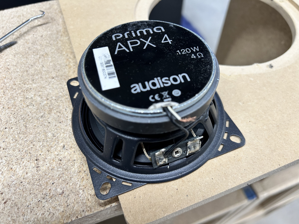
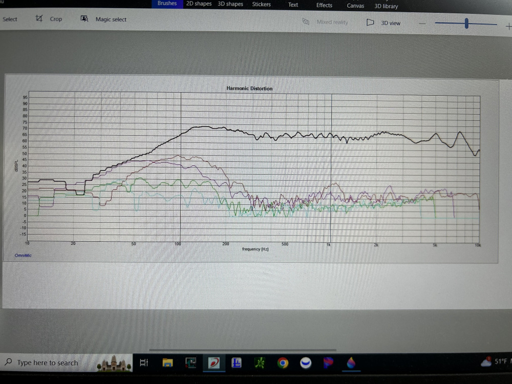
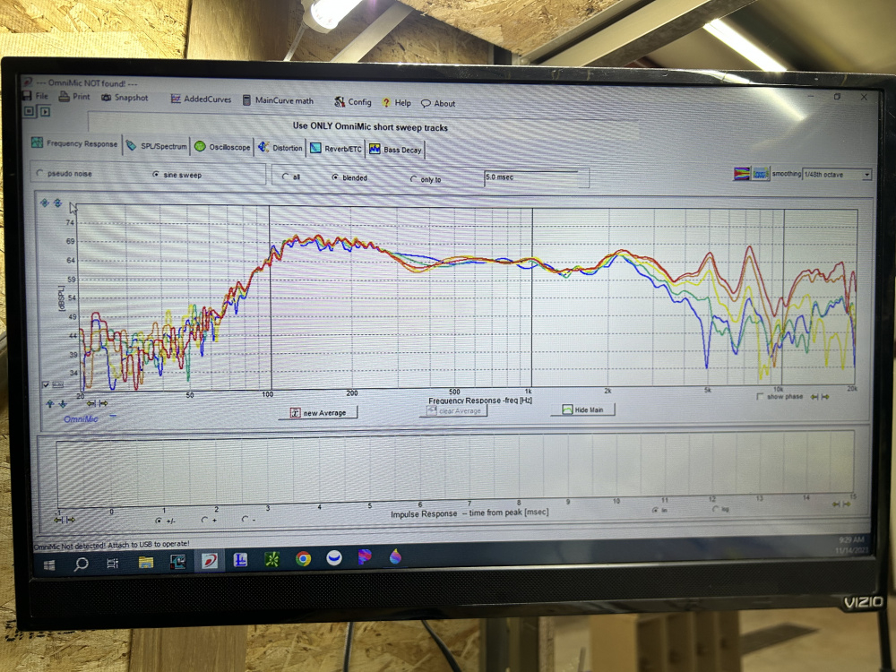
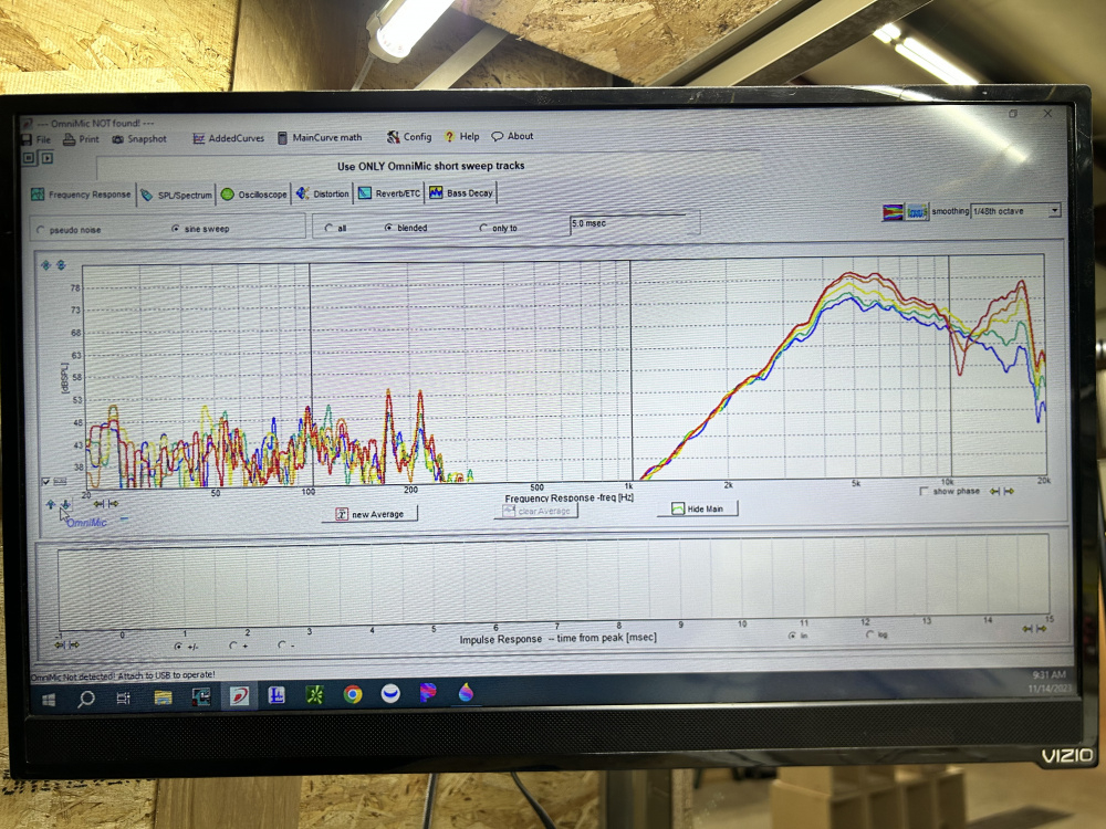
I was hoping for way better than this.
https://www.jfcomponents.com/
Chinese H-02-04
https://www.jfcomponents.com/
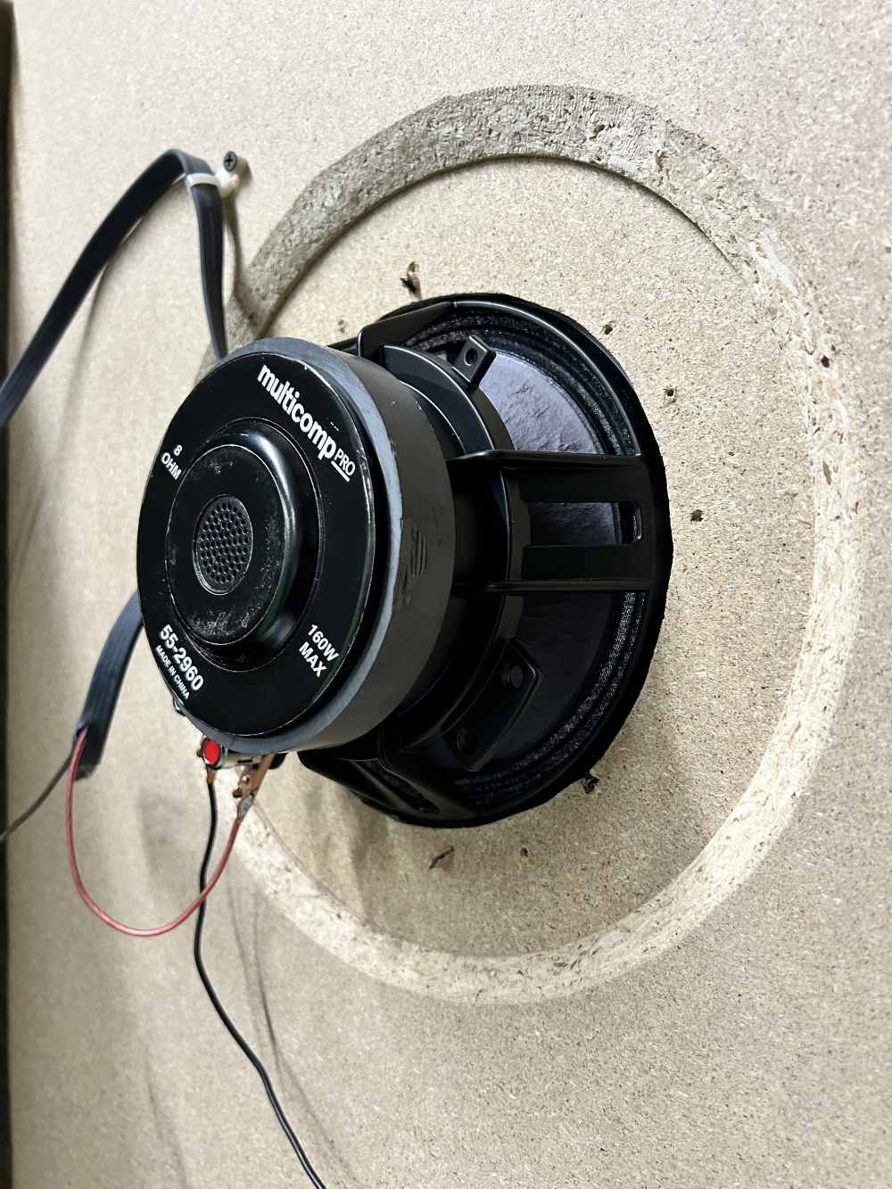
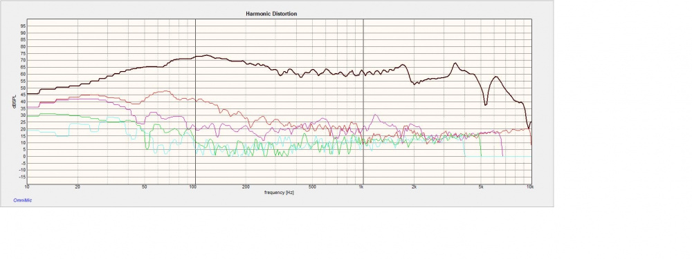
Multicomp 8” 55-2960
https://www.jfcomponents.com/
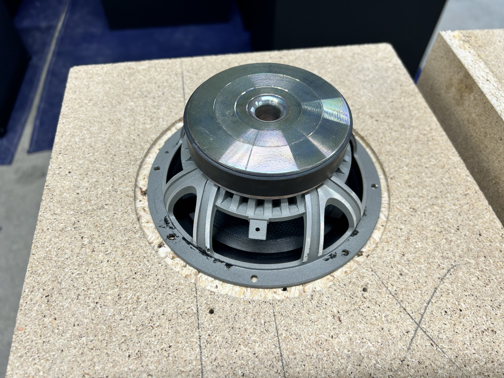
Sony XS-gs80L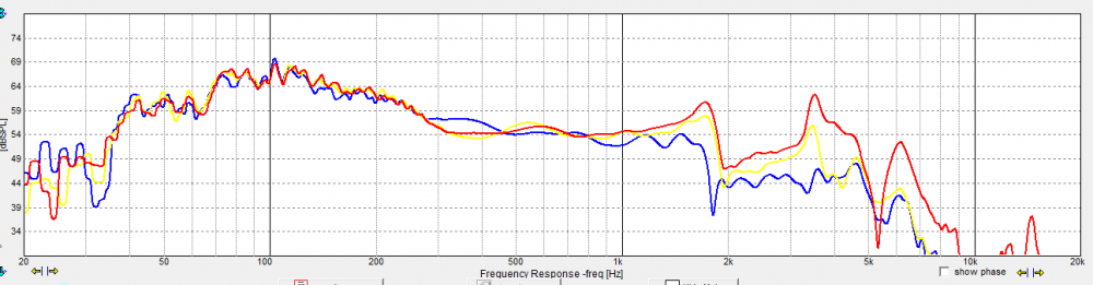
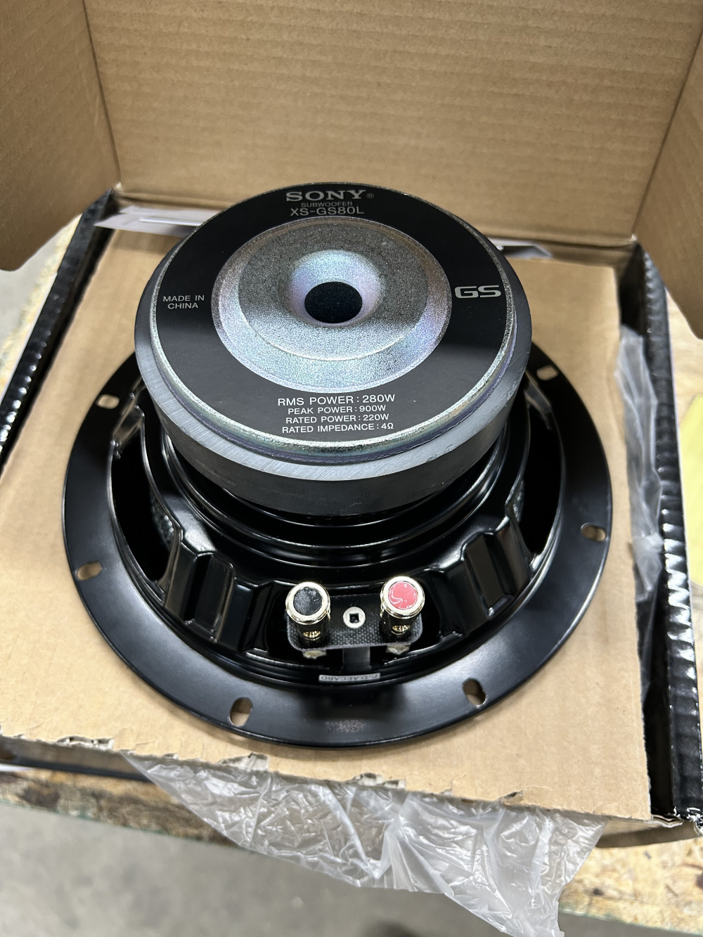
Higher Q subwoofer.
https://www.jfcomponents.com/