@ani_101 said:
does it climb stairs? i need something that is good for going up and down stairs...
The 10 inch wheels help with the stairs, but it's still quite a bit of effort. This just gives me a better chance of not dinging the speaker. Personally, I'd seek help if a speaker was over 100 Lbs or so. But trying to not build something that big ever.
But Chahly - Stahkist don't want speakers that look good, Stahkist wants speakers that sound good!
There are electric stair climbing dollies that cost from $2K to $4K. I was looking at ways to move tools and furniture into the basement. I decided after being pulled down the stairs by a cabinet on a big wheeled dolly that I'm calling a mover.
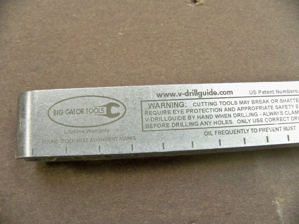
I use this for drilling the centering pin for my circle jig.
This one is an adjustable t-square, I don't really use it building speakers, but it's handy for mounting drawer slides in cabinets.
I made my own saw jig using aluminum channel I bought on Amazon and a saw I picked up at the pawn shop. It's just a fancy version of the standard saw jig. The channel keep the saw from wondering away from the fence.
Cool! I was just about to build my own sawboard, but the aluminum channel looks like a much better solution than 1/4 BB plywood. Is that a standard T-track, or something else? Got a link? thanks.
But Chahly - Stahkist don't want speakers that look good, Stahkist wants speakers that sound good!
Finally got around to rebuilding my measurement jig. Had the parts lying around for ages. Cheap locking 1/4" TRS jacks for connection, amp input is on the back. Box is large considering what's inside, but it does the trick.
@dcibel said:
Finally got around to rebuilding my measurement jig. Had the parts lying around for ages. Cheap locking 1/4" TRS jacks for connection, amp input is on the back. Box is large considering what's inside, but it does the trick.
Similar to the arta/limp jig for 2 channel measurement with some corners cut. I don't switch the mic through the jig, when I use the mic I simply disconnect the impedance probe from my audio interface and plug in the mic instead. The switch on the jig for SPL bypasses the 10 ohm resistor that's inside for impedance measurements. As well, I don't have a switch for calibration since all you really need to do is disconnect the load for that.
@dcibel said:
Similar to the arta/limp jig for 2 channel measurement with some corners cut. I don't switch the mic through the jig, when I use the mic I simply disconnect the impedance probe from my audio interface and plug in the mic instead. The switch on the jig for SPL bypasses the 10 ohm resistor that's inside for impedance measurements. As well, I don't have a switch for calibration since all you really need to do is disconnect the load for that.
Is the amp connected for the impedance measurement? I need to build a amplified limp measurement jig, but not very clear on the limp documentation on how to go about doing it
For limp you can connect with or without an amp, the jig connection should be slightly different depending on your method.
For myself, I prefer to always connect the amp, and it makes the jig a bit simpler overall.
The different connections for LIMP are explained in the help file, for direct soundcard input you should use a high resistor value since the soundcard needs a high impedance load. You can use a lower resistor value with a power amp, 27 ohms in the Limp document, I use 10 Ohm in my jig. The zeners are optional, only needed if you're prone to doing silly things, I've never included them and rely on the level meter in Arta/Limp and the clipping indicator on my audio interface.
If it helps I'll draw out my circuit exactly for you a bit later on today.
I use a Steinberg UR22mkii, its portable, convenient and includes 48V phantom power for the mic.
My amp is a DIY LM3886 thing, but you can use almost any old amp you have lying around. Low power class-D solutions are usually BTL internally which cannot be used. The negative reference of the amp must be at the same potential as the negative reference of the soundcard, as you can see the probe resistors connect to ground, as does the speaker. This will not be the case with a bridged amp.
thanks, will use an AB amp, like the Dayton APA-150 or the emotiva A-100 that's typically what i use for measurements.
I didn't quite understand this "The negative reference of the amp must be at the same potential as the negative reference of the soundcard, as you can see the probe resistors connect to ground, as does the speaker. This will not be the case with a bridged amp"
I can use the same values? No amp voltage / impedance / resistance matching required? this sort of threw me off with all the calculations that followed - reading again it seems all that was for the voltage divider - so if this can be ignored, great - just don't dial it up to 11?
This looks simple enough to construct.
How does this connect to the sound card? Audio out to amp in mono (or the left channel as shown below), and then audio in - what is the Reference and Impedance probe?
Also, what is connected in case of the SPL switch - is this just powering the speaker and the reference probe and impedance probe are disconnected from the sound card? I am going to order a cheap usb sound card to test out.
You can use the same values...reference resistor can be really anywhere from 10 to 400 ohms. The low resistance makes the measurement more of a "voltage source", where high resistance makes the measurement more of a "current source" but any half decent amp should have no difference here. The specific value isn't super important here, but knowing what it is exactly is important, you need to enter the resistor value into ARTA preferences or nothing will be right.
The voltage probe is a voltage divider, provides attenuation to bring the speaker level voltage down to line level. The calculations are all explained in the ARTA application note for the jig...I've attached a spreadsheet to calculate as well. The values chosen for the probes determine the attenuation, and also the maximum power that you can drive into the speaker before you start clipping the soundcard input.
How does it connect - reference goes to one channel, impedance probe goes in the other. Which one goes in Left or right, it doesn't matter for ARTA/Limp as long as you select it properly in the preferences.
When I switch to SPL, the 10 ohm resistor is bypassed, reference probe remains connected. I remove the impedance probe and connect the mic directly to my audio interface. XLR mic and the jig makes for a 2 channel measurement system, much superior for speaker design to single channel USB mics that most people use. When a measurement is made, 2 impulses are recorded. 1 from the mic, and 1 from the reference probe which is the amplifier output. This provides a timing reference, so the start of the FFT window can be locked, any distance offsets between measurements can be maintained simply by keeping the mic distance from the baffle the same and locking the timing reference. No need to determine offsets, the delays will be included in the measurement.
The reference also allows the measurement to compensate for any non-linearity before the reference probe. So any non-linearity in amp output like some class-D options, or if you need a cap to protect your tweeter but don't want to affect the measured SPL, just place the cap before the reference probe, in my case, the cap just goes on the amp input side of the jig.
If you're looking at cheap USB soundcard options, do not buy Behringer UCA202 its junk. The cheap USB audio interface that I'd look at would be the Behringer UMC202HD.
Thanks for the detailed explanation - i will go through the Arta guide. Question on the 2 channel SPL measurement - do you use ARTA or some other sw for measuring? I am not sure which s/w are capable of conducting 2 channel measurements.
I recently purchased an ARTA license, so yes I'm using ARTA now. The jig and measurement setup here is the same for SoundEasy as well.
REW doesn't do a true 2 channel measurement, but it will let you set up the reference channel as a timing reference which is the most important part. REW doesn't record the reference channel impulse and does no frequency response compensation as a result, it's strictly a timing reference. I'm not that familiar with REW, but I know there's some how to information on using it in this fashion in the VituixCAD documentation here:
In the excel sheet, everything is derived off the R1, R2 and Soundcard input resistance. R1, R2 and all the resistors I can measure and input the values - how to measure the soundcard input? Or is it a theoretical number since its set to 10,000 ohms? Any way to check what voltage the amp is outputting?
Also, what type of resistors to use - are there any good or better ones that i can then measure with a multi-meter and enter the appropriate values into Arta.
The Arta demo mode is free but need to check if I can export the FRD file. Don't really need to save the measurements to start off.
The only thing the demo version of ARTA prevents is saving your session. It is really a non-issue, as you can export the FRD/ZMA and take screenshots. Otherwise, it allows you to use every feature without limit.
I did buy a license several years ago, because the developer deserves it and it was about $150 at the time IIRC.
i'll try it and buy the license - looks like its 79Euros for the personal and 149 Euro for the commercial license - pretty reasonable. Sound easy and omini mic were the other ones on my list. But i need to get set on only one else i am just fluttering between multiple choices and getting frustrated. Also need to find a good stable alternative for PCD.
@ani_101 said:
In the excel sheet, everything is derived off the R1, R2 and Soundcard input resistance. R1, R2 and all the resistors I can measure and input the values - how to measure the soundcard input? Or is it a theoretical number since its set to 10,000 ohms? Any way to check what voltage the amp is outputting?
Also, what type of resistors to use - are there any good or better ones that i can then measure with a multi-meter and enter the appropriate values into Arta.
The Arta demo mode is free but need to check if I can export the FRD file. Don't really need to save the measurements to start off.
Don't get too hung up on the resistor values, especially if your primarily wanting T/S data. For that your amp should be low level 100mV or so output. Where the limits come into play is high power distortion testing, otherwise just need to be able to provide the speaker with a couple volts for frequency response data without overloading the input.
You should be fine with the 47k/22k that I use or the 8.5k/910 or whatever is in the ARTA docs. Standard 1/4w 1% resistors are fine, the calibration will take care of the rest. I use a 5W resistor for the 10 ohm value, check with a good meter and enter the measured value into Limp.
Look in the specs of your sound device for the input impedance and sensitivity. 10k is fairly common.
Check what voltage? A multimeter, use the signal generator in the software. Again, don't get too hung up on the specifics unless you're hitting the limits. Use the level meters in ARTA/Limp to set things up, if using a USB audio Interface like I suggest, they usually have clipping indicators on them.
You can do a lot in demo mode, license is $100 which will let you save the impulse response files, nice feature to have. If you follow the VituixCAD process posted above, saving the impulse allows for bulk processing of off-axis data within VituixCAD.
Thanks, i'll build it and revert back and start a new thread. Amazon seems to have the UMC204HD in stock and cheaper than the UMC202HD which only a used one is there. Are they comparable or the UMC202HD is better? They appear to be from the same family, except has two more outputs.
The 204 has 4 of outputs, you may not need them, but if it's a better deal for you go for it.
If you're going that route, get a couple 1/4" patch cables with it, and you can build your jig with 1/4" TRS jacks like I did. The great thing about doing this, is the 48V phantom power for the mic is only on the XLR pins, so when you plug in with TRS plugs there's no worry of hitting anything with 48V if you leave the phantom power turned on.
@ani_101 said:
i'll try it and buy the license - looks like its 79Euros for the personal and 149 Euro for the commercial license - pretty reasonable. Sound easy and omini mic were the other ones on my list. But i need to get set on only one else i am just fluttering between multiple choices and getting frustrated. Also need to find a good stable alternative for PCD.
I agree that all you need is 1 good program. I have Omnimic, but still use ARTA occasionally, and use LIMP for all my ZMA measurements. I like the ability to change the colors in the ARTA graphs, and I really like the distortion measurements in ARTA that will show % instead of just dB levels of the distortion. With a USB soundcard, it should be as easy to setup as Omnimic.
And I'm a BIG fan of Bill Waslo's Xsim for crossover development.
But Chahly - Stahkist don't want speakers that look good, Stahkist wants speakers that sound good!
Omnimic is a good tool, I still use mine as an easy plug and play option for in-room measurements. For the design work, the 2 channel system with ARTA is vastly superior IMO, and you get all the impedance and tsp data with the same jig, no need for the DATS dongle.
Comments
Those are called "appliance dollies".
The 10 inch wheels help with the stairs, but it's still quite a bit of effort. This just gives me a better chance of not dinging the speaker. Personally, I'd seek help if a speaker was over 100 Lbs or so. But trying to not build something that big ever.
There are electric stair climbing dollies that cost from $2K to $4K. I was looking at ways to move tools and furniture into the basement. I decided after being pulled down the stairs by a cabinet on a big wheeled dolly that I'm calling a mover.
I use this for drilling the centering pin for my circle jig.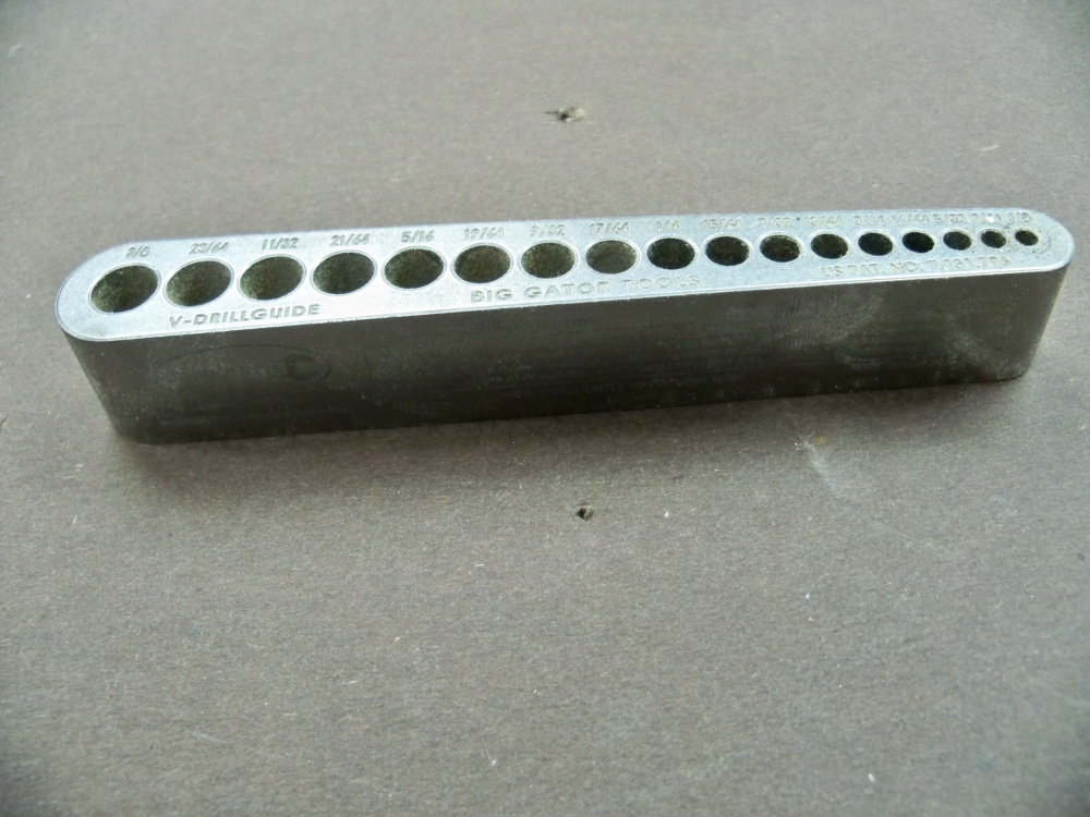
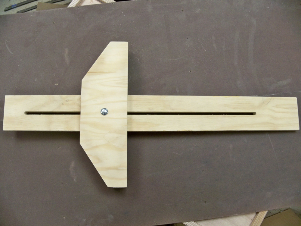
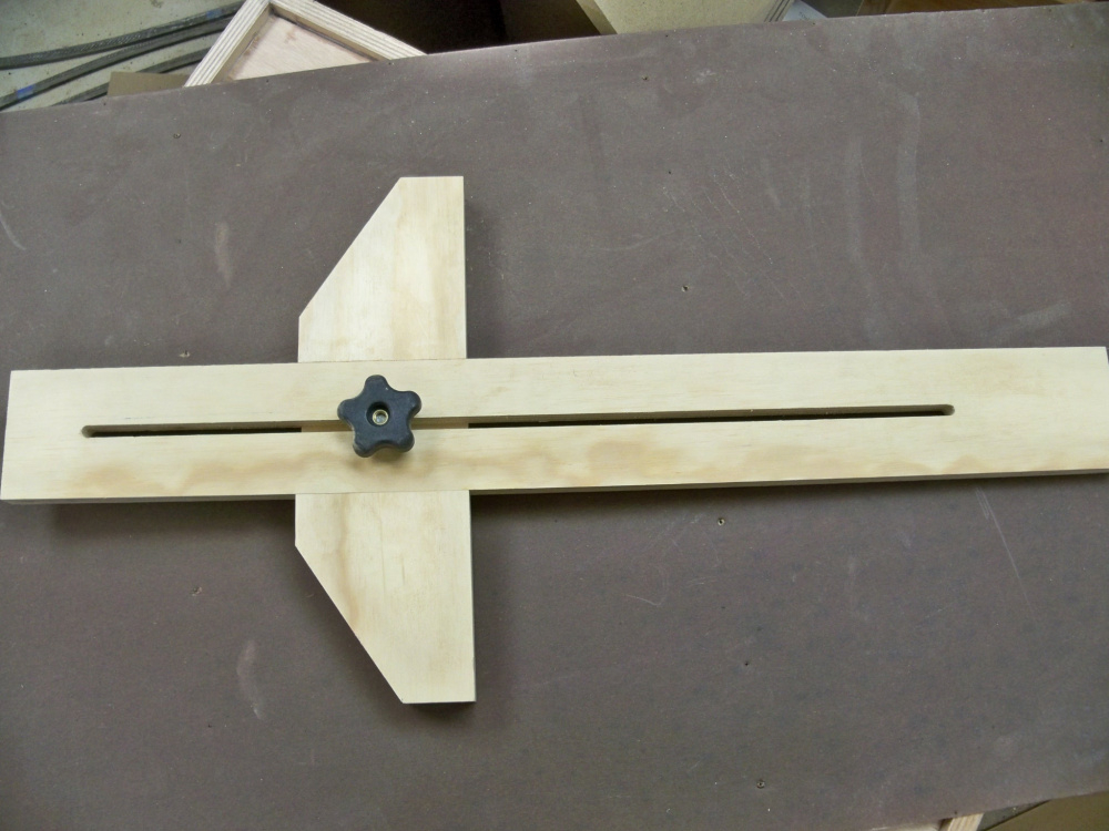
This one is an adjustable t-square, I don't really use it building speakers, but it's handy for mounting drawer slides in cabinets.
I made my own saw jig using aluminum channel I bought on Amazon and a saw I picked up at the pawn shop. It's just a fancy version of the standard saw jig. The channel keep the saw from wondering away from the fence.
Ron
Cool! I was just about to build my own sawboard, but the aluminum channel looks like a much better solution than 1/4 BB plywood. Is that a standard T-track, or something else? Got a link? thanks.
This is what I bought and they don't currently have it in stock.
https://amazon.com/ALUMINUM-MITER-T-TRACK-Peachtree-Woodworking/dp/B000KV14PY
This looks very similar.
https://amazon.com/dp/B07JZ79SSN/ref=dp_prsubs_3
Ron
Sweet, I hadn't see that locking T-Bar rail before. Simplifies a whole of jigs.
Finally got around to rebuilding my measurement jig. Had the parts lying around for ages. Cheap locking 1/4" TRS jacks for connection, amp input is on the back. Box is large considering what's inside, but it does the trick.
Is this based on the limp jig?
Similar to the arta/limp jig for 2 channel measurement with some corners cut. I don't switch the mic through the jig, when I use the mic I simply disconnect the impedance probe from my audio interface and plug in the mic instead. The switch on the jig for SPL bypasses the 10 ohm resistor that's inside for impedance measurements. As well, I don't have a switch for calibration since all you really need to do is disconnect the load for that.
Is the amp connected for the impedance measurement? I need to build a amplified limp measurement jig, but not very clear on the limp documentation on how to go about doing it
For limp you can connect with or without an amp, the jig connection should be slightly different depending on your method.
For myself, I prefer to always connect the amp, and it makes the jig a bit simpler overall.
The different connections for LIMP are explained in the help file, for direct soundcard input you should use a high resistor value since the soundcard needs a high impedance load. You can use a lower resistor value with a power amp, 27 ohms in the Limp document, I use 10 Ohm in my jig. The zeners are optional, only needed if you're prone to doing silly things, I've never included them and rely on the level meter in Arta/Limp and the clipping indicator on my audio interface.
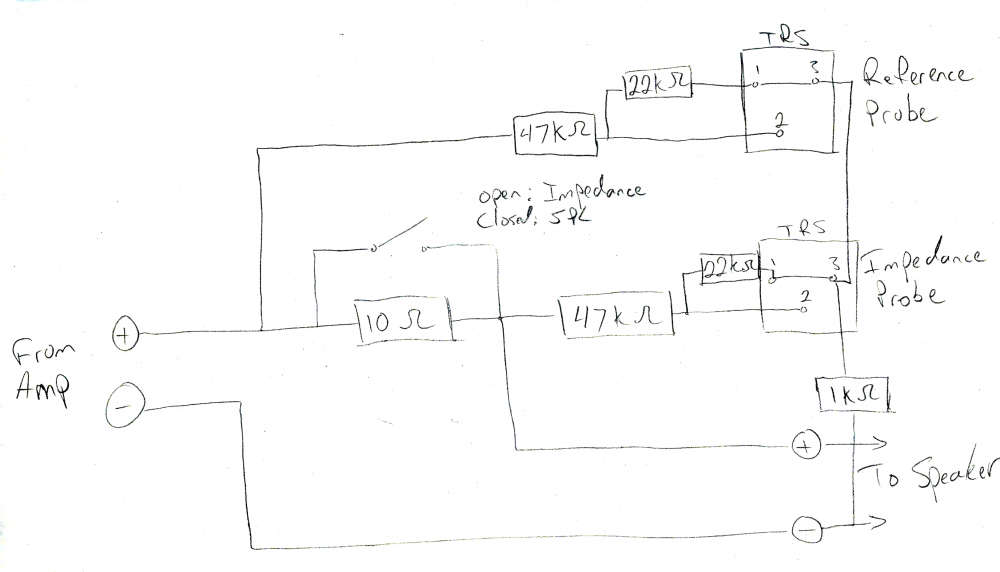
If it helps I'll draw out my circuit exactly for you a bit later on today.
Thanks, that would be very helpful. What amp and soundcard are you using?
I use a Steinberg UR22mkii, its portable, convenient and includes 48V phantom power for the mic.
My amp is a DIY LM3886 thing, but you can use almost any old amp you have lying around. Low power class-D solutions are usually BTL internally which cannot be used. The negative reference of the amp must be at the same potential as the negative reference of the soundcard, as you can see the probe resistors connect to ground, as does the speaker. This will not be the case with a bridged amp.
thanks, will use an AB amp, like the Dayton APA-150 or the emotiva A-100 that's typically what i use for measurements.
I didn't quite understand this "The negative reference of the amp must be at the same potential as the negative reference of the soundcard, as you can see the probe resistors connect to ground, as does the speaker. This will not be the case with a bridged amp"
Don't use a Bridged "BTL" amp, the negative speaker terminal will not be 0V. Best case bad measurement, worst case damaged equipment.
Best ARTA jig schematic ever..")
If you want to use RCA instead of TRS, pin 2 is RCA tip, pin 1 is RCA shield.
Thanks! this is great...
I can use the same values? No amp voltage / impedance / resistance matching required? this sort of threw me off with all the calculations that followed - reading again it seems all that was for the voltage divider - so if this can be ignored, great - just don't dial it up to 11?
This looks simple enough to construct.
How does this connect to the sound card? Audio out to amp in mono (or the left channel as shown below), and then audio in - what is the Reference and Impedance probe?
Also, what is connected in case of the SPL switch - is this just powering the speaker and the reference probe and impedance probe are disconnected from the sound card? I am going to order a cheap usb sound card to test out.
You can use the same values...reference resistor can be really anywhere from 10 to 400 ohms. The low resistance makes the measurement more of a "voltage source", where high resistance makes the measurement more of a "current source" but any half decent amp should have no difference here. The specific value isn't super important here, but knowing what it is exactly is important, you need to enter the resistor value into ARTA preferences or nothing will be right.
The voltage probe is a voltage divider, provides attenuation to bring the speaker level voltage down to line level. The calculations are all explained in the ARTA application note for the jig...I've attached a spreadsheet to calculate as well. The values chosen for the probes determine the attenuation, and also the maximum power that you can drive into the speaker before you start clipping the soundcard input.
How does it connect - reference goes to one channel, impedance probe goes in the other. Which one goes in Left or right, it doesn't matter for ARTA/Limp as long as you select it properly in the preferences.
When I switch to SPL, the 10 ohm resistor is bypassed, reference probe remains connected. I remove the impedance probe and connect the mic directly to my audio interface. XLR mic and the jig makes for a 2 channel measurement system, much superior for speaker design to single channel USB mics that most people use. When a measurement is made, 2 impulses are recorded. 1 from the mic, and 1 from the reference probe which is the amplifier output. This provides a timing reference, so the start of the FFT window can be locked, any distance offsets between measurements can be maintained simply by keeping the mic distance from the baffle the same and locking the timing reference. No need to determine offsets, the delays will be included in the measurement.
The reference also allows the measurement to compensate for any non-linearity before the reference probe. So any non-linearity in amp output like some class-D options, or if you need a cap to protect your tweeter but don't want to affect the measured SPL, just place the cap before the reference probe, in my case, the cap just goes on the amp input side of the jig.
If you're looking at cheap USB soundcard options, do not buy Behringer UCA202 its junk. The cheap USB audio interface that I'd look at would be the Behringer UMC202HD.
Thanks for the detailed explanation - i will go through the Arta guide. Question on the 2 channel SPL measurement - do you use ARTA or some other sw for measuring? I am not sure which s/w are capable of conducting 2 channel measurements.
I recently purchased an ARTA license, so yes I'm using ARTA now. The jig and measurement setup here is the same for SoundEasy as well.
REW doesn't do a true 2 channel measurement, but it will let you set up the reference channel as a timing reference which is the most important part. REW doesn't record the reference channel impulse and does no frequency response compensation as a result, it's strictly a timing reference. I'm not that familiar with REW, but I know there's some how to information on using it in this fashion in the VituixCAD documentation here:
https://kimmosaunisto.net/Software/VituixCAD/VituixCAD_Measurement_Preparations_REW.pdf
Similar document for ARTA here:
https://kimmosaunisto.net/Software/VituixCAD/VituixCAD_Measurement_Preparations_REW.pdf
Similar document for SoundEasy here:
https://kimmosaunisto.net/Software/VituixCAD/VituixCAD_Measurement_SoundEasy.pdf
In the excel sheet, everything is derived off the R1, R2 and Soundcard input resistance. R1, R2 and all the resistors I can measure and input the values - how to measure the soundcard input? Or is it a theoretical number since its set to 10,000 ohms? Any way to check what voltage the amp is outputting?
Also, what type of resistors to use - are there any good or better ones that i can then measure with a multi-meter and enter the appropriate values into Arta.
The Arta demo mode is free but need to check if I can export the FRD file. Don't really need to save the measurements to start off.
The only thing the demo version of ARTA prevents is saving your session. It is really a non-issue, as you can export the FRD/ZMA and take screenshots. Otherwise, it allows you to use every feature without limit.
I did buy a license several years ago, because the developer deserves it and it was about $150 at the time IIRC.
i'll try it and buy the license - looks like its 79Euros for the personal and 149 Euro for the commercial license - pretty reasonable. Sound easy and omini mic were the other ones on my list. But i need to get set on only one else i am just fluttering between multiple choices and getting frustrated. Also need to find a good stable alternative for PCD.
Don't get too hung up on the resistor values, especially if your primarily wanting T/S data. For that your amp should be low level 100mV or so output. Where the limits come into play is high power distortion testing, otherwise just need to be able to provide the speaker with a couple volts for frequency response data without overloading the input.
You should be fine with the 47k/22k that I use or the 8.5k/910 or whatever is in the ARTA docs. Standard 1/4w 1% resistors are fine, the calibration will take care of the rest. I use a 5W resistor for the 10 ohm value, check with a good meter and enter the measured value into Limp.
Look in the specs of your sound device for the input impedance and sensitivity. 10k is fairly common.
Check what voltage? A multimeter, use the signal generator in the software. Again, don't get too hung up on the specifics unless you're hitting the limits. Use the level meters in ARTA/Limp to set things up, if using a USB audio Interface like I suggest, they usually have clipping indicators on them.
You can do a lot in demo mode, license is $100 which will let you save the impulse response files, nice feature to have. If you follow the VituixCAD process posted above, saving the impulse allows for bulk processing of off-axis data within VituixCAD.
Thanks, i'll build it and revert back and start a new thread. Amazon seems to have the UMC204HD in stock and cheaper than the UMC202HD which only a used one is there. Are they comparable or the UMC202HD is better? They appear to be from the same family, except has two more outputs.
https://www.amazon.com/Behringer-UMC202HD-BEHRINGER-U-PHORIA-2-Channel/dp/B00QHURUBE/ref=sr_1_28?dchild=1&keywords=UMC202HD&qid=1611240106&s=musical-instruments&sr=1-28&th=1
https://www.amazon.com/Behringer-UMC204HD-U-Phoria/dp/B00WMKC9OG/ref=pd_all_pref_6?pd_rd_w=UN3f5&pf_rd_p=e6474b7e-8fb6-4ee2-b5d6-a1da55185fe6&pf_rd_r=MJ7GSNMMCSN24VJ0XYTR&pd_rd_r=70bb8c02-fe2a-437b-a7ee-bc64da8a99fb&pd_rd_wg=9YatQ&pd_rd_i=B00WMKC9OG&psc=1
The 204 has 4 of outputs, you may not need them, but if it's a better deal for you go for it.
If you're going that route, get a couple 1/4" patch cables with it, and you can build your jig with 1/4" TRS jacks like I did. The great thing about doing this, is the 48V phantom power for the mic is only on the XLR pins, so when you plug in with TRS plugs there's no worry of hitting anything with 48V if you leave the phantom power turned on.
I agree that all you need is 1 good program. I have Omnimic, but still use ARTA occasionally, and use LIMP for all my ZMA measurements. I like the ability to change the colors in the ARTA graphs, and I really like the distortion measurements in ARTA that will show % instead of just dB levels of the distortion. With a USB soundcard, it should be as easy to setup as Omnimic.
And I'm a BIG fan of Bill Waslo's Xsim for crossover development.
Omnimic is a good tool, I still use mine as an easy plug and play option for in-room measurements. For the design work, the 2 channel system with ARTA is vastly superior IMO, and you get all the impedance and tsp data with the same jig, no need for the DATS dongle.
I like Omni mic for the real time FR display and the SPL calibrated mic. When I used ARTA I'd have to convert from impulse to FR.