Potting 0.15mH now. Just laid the label underneath the resin on these. No need for the zip tie. Already had the previous ones made, and figured I'd try it. This will make mounting these easier. The golf tee is a place to bore for the mounting screws, and a grip upon removal.
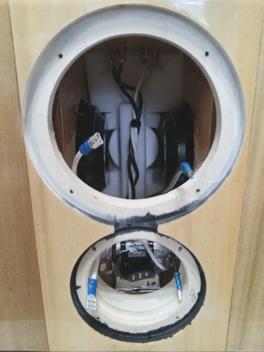
Looks like I can get all but 2 tweeter parts in the bottom with only 3 short jumpers. The 2 tweeter coils are an inch apart, and I've been good at that distance before for air cores. The foil has a different field due to how it's wound I believe, but I might be mistaken. I will likely mount the large parts and leave the resistors open for adjustment. That way I can adjust when using the SB12. Rubber feet on rails will give me the required clearance. Stainless screws mount the coils for no ferrous interaction- I checked!
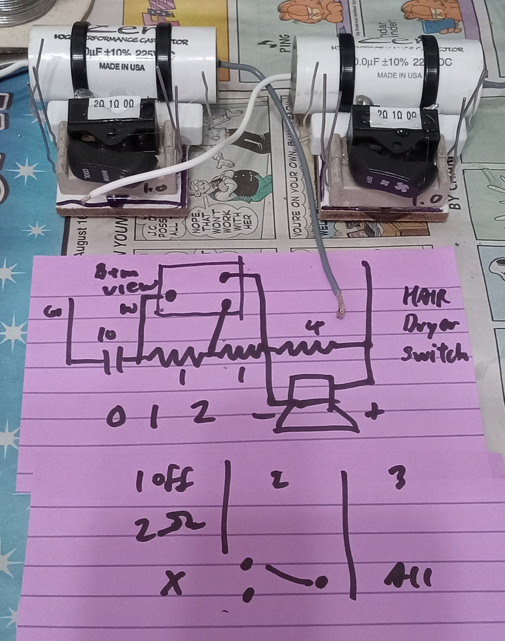
This is the plan for tweeter attenuation. Had some scavenged hair dryer switches that will do nicely. I don't know the switch acronym, but it's an Off-1-(1+2) type 3 position, 3 terminal switch. Like an SPDT, but with the second throw also connecting to the first. The switch will set additional 0,1, or 2 ohms to the tweeter by shorting 1 or both resistors all connected in series. This is the tiny board that mounts to the inside top behind the tweeter using strong 3M plastic toothed velcro.
Sounds like a triple throw switch with 1ohm resistors connecting the outer contacts to the center second position. The input or output then connects to one of the outer contacts positions and switched contact.
3 position, single pole, dual throw, but not an SPDT, and the 3rd position contacts the single pole to both output throws. Whether the center terminal is terminal 0 or the 'terminal by itself' is irrelevant to operation in this matter, as both connect either way. The throws are linked to the singled terminal, and throw towards to the 2 at the dual end. It's an open case style, so I can see the works.
It's actually a thought about more with this project. The SB12CAC-4 and maybe the Glass Fiber Wavecor midbasses I also have.
More adjustments mean easier blending. The 15 ohm series resistor and the 4 ohm parallel resistor are the main players. I'll need less of the 15 on the other 2 options, but the 4.0 kills the Fs spike and is kind of needed.
More progress. Tweeter board in place, and view of magic eraser damping sans wool wad:
Nice! It's rewarding when sims and real measurements jive so well. I felt that way when I first measured my Indy theme project and saw both tunings within a Hertz or 2 of their predicted.
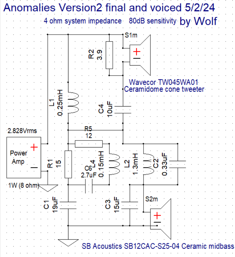
Yep, this is a series xover. The LCR around the 15 ohm reduces the padding to lift the trough the tweeter has. The 15, 1, and 4 ohm are for Fs suppression and padding. 1.3mH is mainly for BSC, the 0.33uF is a tank for breakup. The 10uF and 0.25mH are the tweeter highpass, and the 19uF/1.3mH/15uF/2.4 ohm are the woofer lowpass.
Okay, already done with Version 2 with the SB12CACS25-4. These are a LOT better sounding now. Tonality and timbre of drivers matches better. Dynamics and bass palpability are much improved. Sensitivity went up about 3-4dB.
I used 2 fewer parts to get there, but I didn't need to change anything else! Basically, I reset the resistor switch to bypass both in series, or no attenuation, and removed the damping resistor on the woofer CR shunt. The removal of both lent to the higher sensitivity, and raised a dip in the FR below the xover point to flatten it out. The male vocals were sounding a bit heavy before I changed this, as is to be expected.
To boot, it appears the HD is now lower overall because the sensitivity is higher. There is a second order bump in the bass HD, but below there is actually quite clean. Funny occurrence during the HD sweeps, I had a spot in the bass range where I heard a shift of the bass output, likely in this same range between the 2 tuning frequencies. This was taken at a meter distance on the tweeter axis, and the little midbass would have complained had I gone louder.
Thx for your explanation (previously) re notch filters etc. on your series Xover. Series always looks ‘backwards’ as to which components control which drivers…
@Steve_Lee said:
Its a shame on Kartesian for such poor production of these drivers, Wolf.
Kartesian know exactly what they are doing with these drivers. They already know how they can be improved, as they do so on their higher end variant.
@Wolf
Have you considered giving feedback to Kartesian about these drivers?
IME some manufacturers can be receptive to what people are doing with their products, in the field. In a way they are getting free QC and process improvement. After all, it's real in-box use with a few volts, that's entirely reasonable.
Now if someone sent the drivers 400W and bottomed them out and complained, well that's a different matter.
I filled out a form on their website a while ago and hit submit, and received no reply. The form was stated to be for companies only, but was the only contact point. Apparently, I don't matter enough to tell them that this woofer needs improvement. I made the attempt, so the ball is in their court. I'm not still playing the game awaiting a huddle.
@tajanes said:
Series always looks ‘backwards’ as to which components control which drivers…
It does and it doesn't. If you imagine you are a high freq or a low freq, and travel/trace the circuit with regards to the path of least resistance, then it makes sense.
It works the same way in a parallel xover, except usually there is not a path to take for one freq or the other.
If you are a low freq, you can go through inductors and woofers, and a high frequency can go through caps and tweeters. Resistors only reduce your size, but you can still pass.
So, we'll take V2 as my example. A high freq will start at + Input, go through tweeter, 10uF, 15 ohm and 19uF, AS WELL AS, 0.33uF and 15uF, and out at - Input. In terms of spitballing resistance, one leg has ~17 ohms resistance, and the other leg has 2 ohms resistance. The 0.33uF or such from a tank can be a problem. It allows output bleeding back in at a very high frequency, and if no resistance is present, it can lead to amplifier oscillation or an ultrasonic short. In this instance, the 0.33uF has either 2 ohms driver/resistor load or a lowpass inductor 0.25mH ahead of it. This means it should be fine and not oscillate. I like to have at least 2 ohms in series with an ultrasonic frequency. Usually, amplifiers are not required to push any substantial current in the upper octaves, so 2 ohms should not be problematic above 20k. Most treble will not go through the 0.33uF cap, as it is a high cutoff.
Using V2 again as a low frequency path starting at + input, frequencies will travel through the 0.25mH coil, the 1.3mH coil, the woofer, and to - input. The woofer is a 4 ohm load here, which is acceptable. The impedance Zmin appears to be about 3.4 ohms above system resonances, which is also above my 3 ohms preference.
Now that we have traced it, we can see that the components still work as intended, that the parts we typically think are influencing their respective drivers are really only in a position of bypass inception.
Series xovers usually bypass or short around the drivers that are not in the bandwidth required. This means that the tweeter was effectively 0 ohms placed in series with the woofer circuit. It was in parallel with the 0.25mH coil, and wired in series with the woofer circuit. This is why the circuit is set up like it is, with the drivers in series.
From the other circuit direction, the 15 ohm resistor that attenuates the tweeter in series with the 19uF cap is in parallel with the woofer and its baffle step 1.3mH coil. The 1.3 will increase the impedance of the woofer leg to where the CR is the lesser resistance, and effectively bypass the woofer for almost all but the very high frequencies. Usually the R magnitude is not as high as 15 ohms, but this tweeter was REALLY sensitive and both woofers fairly insensitive.
If I were to remove the 0.33uF, 3.9 ohm, 15uF, and LCR around the 15 ohm padding resistor, the impedance would not settle back to nominal level in the treble and remain at a shelf of higher magnitude. Had this not been a 3rd order electrical connected to the woofer, removing as suggested but saving the 0.33uF cap, the woofer circuit will have a large rising impedance between the Fc of the 0.33uF and 1.3mH components. The 15uF fixes this problem for a more benign impedance. This value can vary largely, as I have had as small as a 1.5uF cap in that position for other projects.
When this technique is used, you can trace circuits to find any shorts, etc.
In parallel xovers, this is why a tank looks like a short without a small resistance present. I found the same on DaveFred's initial tweeter circuit via the same method.
Use your best judgment, and hopefully this was a helpful exercise.
Edit, made it easier to read...
Interesting that the tuning of the first set of PRs is a better match to Fb in cab for the SB12CACS25-4.
I have thought of reducing the rear PR mass to see what it does. In a way as the lower tuning sits, this is more of an EBS or even MLTL alignment for the rear PR.
Comments
Potting 0.15mH now. Just laid the label underneath the resin on these. No need for the zip tie. Already had the previous ones made, and figured I'd try it. This will make mounting these easier. The golf tee is a place to bore for the mounting screws, and a grip upon removal.
InDIYana Event Website
Looks like I can get all but 2 tweeter parts in the bottom with only 3 short jumpers. The 2 tweeter coils are an inch apart, and I've been good at that distance before for air cores. The foil has a different field due to how it's wound I believe, but I might be mistaken. I will likely mount the large parts and leave the resistors open for adjustment. That way I can adjust when using the SB12. Rubber feet on rails will give me the required clearance. Stainless screws mount the coils for no ferrous interaction- I checked!
InDIYana Event Website
Did you leave enough air volume in there for the drivers? Boy - you pack them tight!
Yep, only a resistor and 10uF cap inside, plus drive units, some lining, and a wad of wool.
InDIYana Event Website
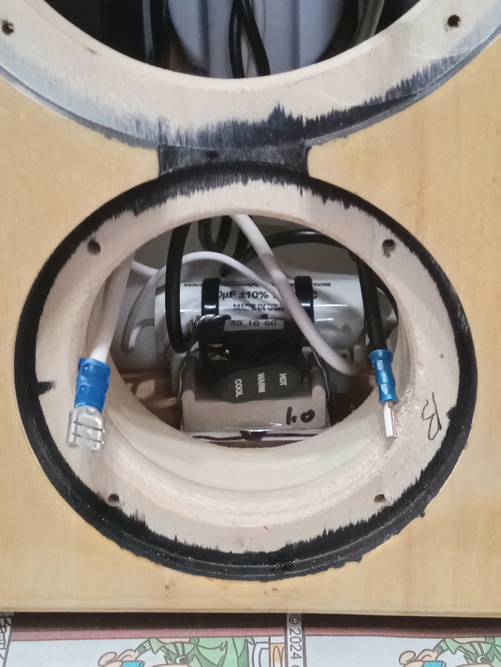
This is the plan for tweeter attenuation. Had some scavenged hair dryer switches that will do nicely. I don't know the switch acronym, but it's an Off-1-(1+2) type 3 position, 3 terminal switch. Like an SPDT, but with the second throw also connecting to the first. The switch will set additional 0,1, or 2 ohms to the tweeter by shorting 1 or both resistors all connected in series. This is the tiny board that mounts to the inside top behind the tweeter using strong 3M plastic toothed velcro.
InDIYana Event Website
Sounds like a triple throw switch with 1ohm resistors connecting the outer contacts to the center second position. The input or output then connects to one of the outer contacts positions and switched contact.
3 position, single pole, dual throw, but not an SPDT, and the 3rd position contacts the single pole to both output throws. Whether the center terminal is terminal 0 or the 'terminal by itself' is irrelevant to operation in this matter, as both connect either way. The throws are linked to the singled terminal, and throw towards to the 2 at the dual end. It's an open case style, so I can see the works.
InDIYana Event Website
So as you age, you remove resistance
It's actually a thought about more with this project. The SB12CAC-4 and maybe the Glass Fiber Wavecor midbasses I also have.
More adjustments mean easier blending. The 15 ohm series resistor and the 4 ohm parallel resistor are the main players. I'll need less of the 15 on the other 2 options, but the 4.0 kills the Fs spike and is kind of needed.
More progress. Tweeter board in place, and view of magic eraser damping sans wool wad:
InDIYana Event Website
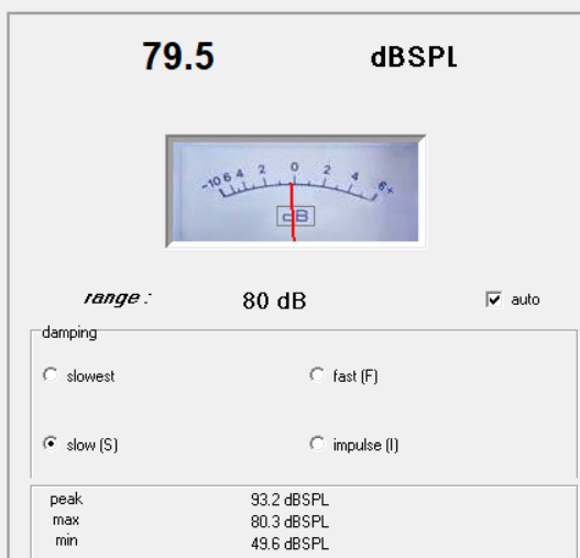
Secondary simulated tunings were set for 40 and 90 Hz according to the impedance graph in the sim. Real tunings yielded 84 and 38Hz. Not bad!

InDIYana Event Website
Nice! It's rewarding when sims and real measurements jive so well. I felt that way when I first measured my Indy theme project and saw both tunings within a Hertz or 2 of their predicted.
Yeah, unlike the DSA135, I didn't have to remove weight on the 8" PRs.
InDIYana Event Website
Ended up adding 1 ohm on the tweeter, just like I thought I would. I took a quick Z, FR, and RTA, just to make sure I'm good.
They're alive!!
InDIYana Event Website
Right on🤘🏼
As being played this weekend...
InDIYana Event Website
That schematic makes my brain hurt, Wolf.
what topology is that? doesn't look 2 way parallel. I am not familiar with other topologies.
Series
Yep, this is a series xover. The LCR around the 15 ohm reduces the padding to lift the trough the tweeter has. The 15, 1, and 4 ohm are for Fs suppression and padding. 1.3mH is mainly for BSC, the 0.33uF is a tank for breakup. The 10uF and 0.25mH are the tweeter highpass, and the 19uF/1.3mH/15uF/2.4 ohm are the woofer lowpass.
InDIYana Event Website
Okay, already done with Version 2 with the SB12CACS25-4. These are a LOT better sounding now. Tonality and timbre of drivers matches better. Dynamics and bass palpability are much improved. Sensitivity went up about 3-4dB.
I used 2 fewer parts to get there, but I didn't need to change anything else! Basically, I reset the resistor switch to bypass both in series, or no attenuation, and removed the damping resistor on the woofer CR shunt. The removal of both lent to the higher sensitivity, and raised a dip in the FR below the xover point to flatten it out. The male vocals were sounding a bit heavy before I changed this, as is to be expected.
To boot, it appears the HD is now lower overall because the sensitivity is higher. There is a second order bump in the bass HD, but below there is actually quite clean. Funny occurrence during the HD sweeps, I had a spot in the bass range where I heard a shift of the bass output, likely in this same range between the 2 tuning frequencies. This was taken at a meter distance on the tweeter axis, and the little midbass would have complained had I gone louder.
The grit:


InDIYana Event Website
InDIYana Event Website
Great you found a simpler Xover with + results.
Thx for your explanation (previously) re notch filters etc. on your series Xover. Series always looks ‘backwards’ as to which components control which drivers…
Kartesian know exactly what they are doing with these drivers. They already know how they can be improved, as they do so on their higher end variant.
@Wolf
Have you considered giving feedback to Kartesian about these drivers?
IME some manufacturers can be receptive to what people are doing with their products, in the field. In a way they are getting free QC and process improvement. After all, it's real in-box use with a few volts, that's entirely reasonable.
Now if someone sent the drivers 400W and bottomed them out and complained, well that's a different matter.
I filled out a form on their website a while ago and hit submit, and received no reply. The form was stated to be for companies only, but was the only contact point. Apparently, I don't matter enough to tell them that this woofer needs improvement. I made the attempt, so the ball is in their court. I'm not still playing the game awaiting a huddle.
InDIYana Event Website
It does and it doesn't. If you imagine you are a high freq or a low freq, and travel/trace the circuit with regards to the path of least resistance, then it makes sense.
It works the same way in a parallel xover, except usually there is not a path to take for one freq or the other.
If you are a low freq, you can go through inductors and woofers, and a high frequency can go through caps and tweeters. Resistors only reduce your size, but you can still pass.
So, we'll take V2 as my example. A high freq will start at + Input, go through tweeter, 10uF, 15 ohm and 19uF, AS WELL AS, 0.33uF and 15uF, and out at - Input. In terms of spitballing resistance, one leg has ~17 ohms resistance, and the other leg has 2 ohms resistance. The 0.33uF or such from a tank can be a problem. It allows output bleeding back in at a very high frequency, and if no resistance is present, it can lead to amplifier oscillation or an ultrasonic short. In this instance, the 0.33uF has either 2 ohms driver/resistor load or a lowpass inductor 0.25mH ahead of it. This means it should be fine and not oscillate. I like to have at least 2 ohms in series with an ultrasonic frequency. Usually, amplifiers are not required to push any substantial current in the upper octaves, so 2 ohms should not be problematic above 20k. Most treble will not go through the 0.33uF cap, as it is a high cutoff.
Using V2 again as a low frequency path starting at + input, frequencies will travel through the 0.25mH coil, the 1.3mH coil, the woofer, and to - input. The woofer is a 4 ohm load here, which is acceptable. The impedance Zmin appears to be about 3.4 ohms above system resonances, which is also above my 3 ohms preference.
Now that we have traced it, we can see that the components still work as intended, that the parts we typically think are influencing their respective drivers are really only in a position of bypass inception.
Series xovers usually bypass or short around the drivers that are not in the bandwidth required. This means that the tweeter was effectively 0 ohms placed in series with the woofer circuit. It was in parallel with the 0.25mH coil, and wired in series with the woofer circuit. This is why the circuit is set up like it is, with the drivers in series.
From the other circuit direction, the 15 ohm resistor that attenuates the tweeter in series with the 19uF cap is in parallel with the woofer and its baffle step 1.3mH coil. The 1.3 will increase the impedance of the woofer leg to where the CR is the lesser resistance, and effectively bypass the woofer for almost all but the very high frequencies. Usually the R magnitude is not as high as 15 ohms, but this tweeter was REALLY sensitive and both woofers fairly insensitive.
If I were to remove the 0.33uF, 3.9 ohm, 15uF, and LCR around the 15 ohm padding resistor, the impedance would not settle back to nominal level in the treble and remain at a shelf of higher magnitude. Had this not been a 3rd order electrical connected to the woofer, removing as suggested but saving the 0.33uF cap, the woofer circuit will have a large rising impedance between the Fc of the 0.33uF and 1.3mH components. The 15uF fixes this problem for a more benign impedance. This value can vary largely, as I have had as small as a 1.5uF cap in that position for other projects.
When this technique is used, you can trace circuits to find any shorts, etc.
In parallel xovers, this is why a tank looks like a short without a small resistance present. I found the same on DaveFred's initial tweeter circuit via the same method.
Use your best judgment, and hopefully this was a helpful exercise.
Edit, made it easier to read...
InDIYana Event Website
Thx for the details- I’ll need to walk through this more than twice…
Appreciate your response!
My head hurts.
Measured impedance of Anomalies V2
InDIYana Event Website
Interesting that the tuning of the first set of PRs is a better match to Fb in cab for the SB12CACS25-4.
I have thought of reducing the rear PR mass to see what it does. In a way as the lower tuning sits, this is more of an EBS or even MLTL alignment for the rear PR.
InDIYana Event Website
That cac driver is a gem. Every time I've heard one of the cac drivers I've been really impressed.